Exercise bar attachment and method

a technology for attaching and removing equipment, applied in the field of exercise equipment, can solve the problems of inability to mount, install, or reconfigure the exercise space, in general, not easy to do, and no currently available equipment that is sturdy, and achieve the effect of convenient attaching and removing

Active Publication Date: 2012-06-07
JFXD TRX ACQ LLC
View PDF8 Cites 52 Cited by
  • Summary
  • Abstract
  • Description
  • Claims
  • Application Information

AI Technical Summary

Benefits of technology

[0007]The present invention overcomes the disadvantages of the prior art by providing exercise bars that are easily attachable and removable onto angled support members, such as an A-frame, or to similarly angled elements capable of supporting the bars.

Problems solved by technology

While there are some devices which allow for reconfiguring equipment, the mounting, assembly, or reconfiguration exercise space is not, in general, easily done.
Specifically, there is no currently available equipment that is sturdy and which allows a user to quickly and easily add or configure bars for a pull up or dip station.

Method used


Image

  • Exercise bar attachment and method
  • Exercise bar attachment and method
  • Exercise bar attachment and method

Examples


first embodiment

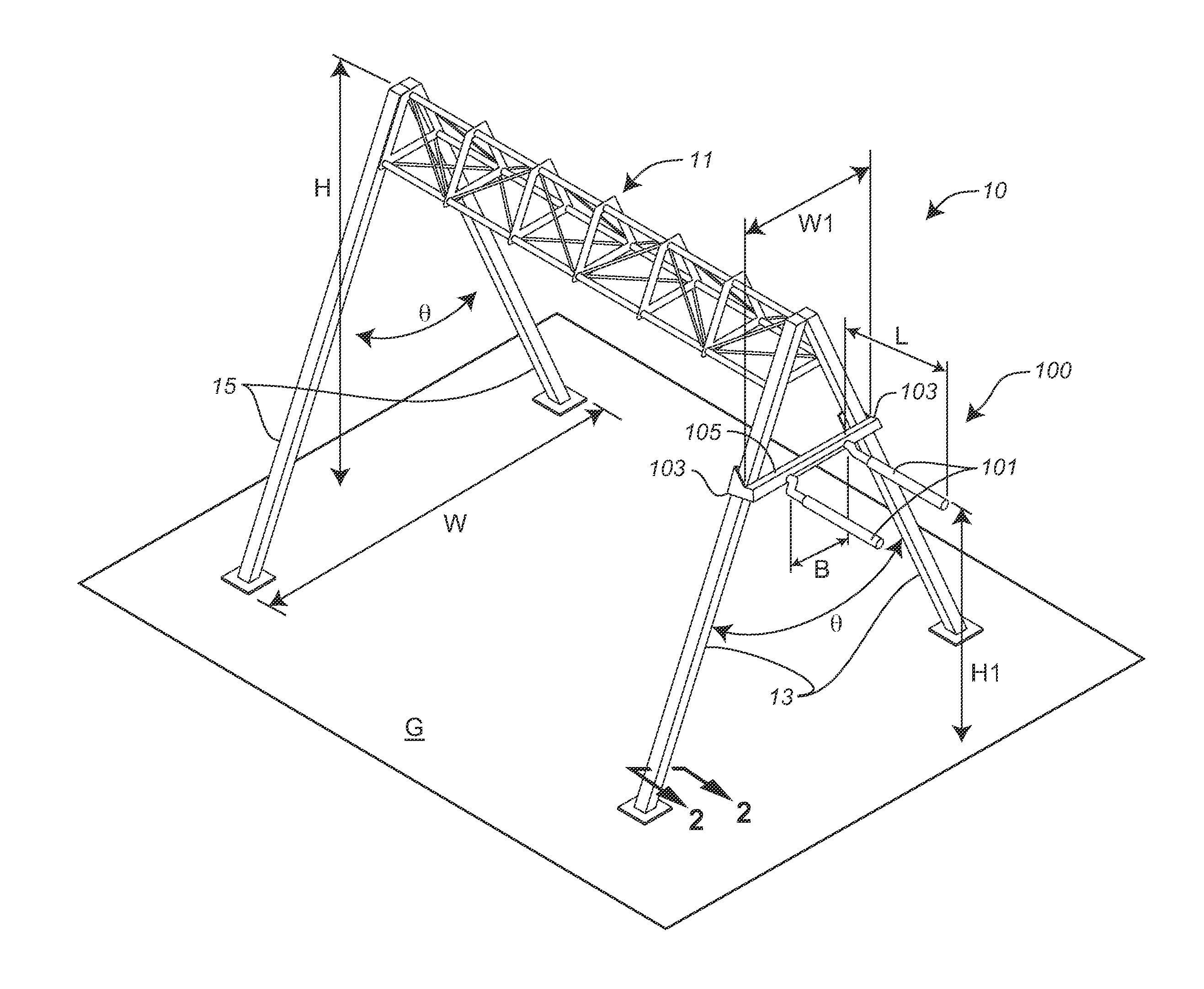
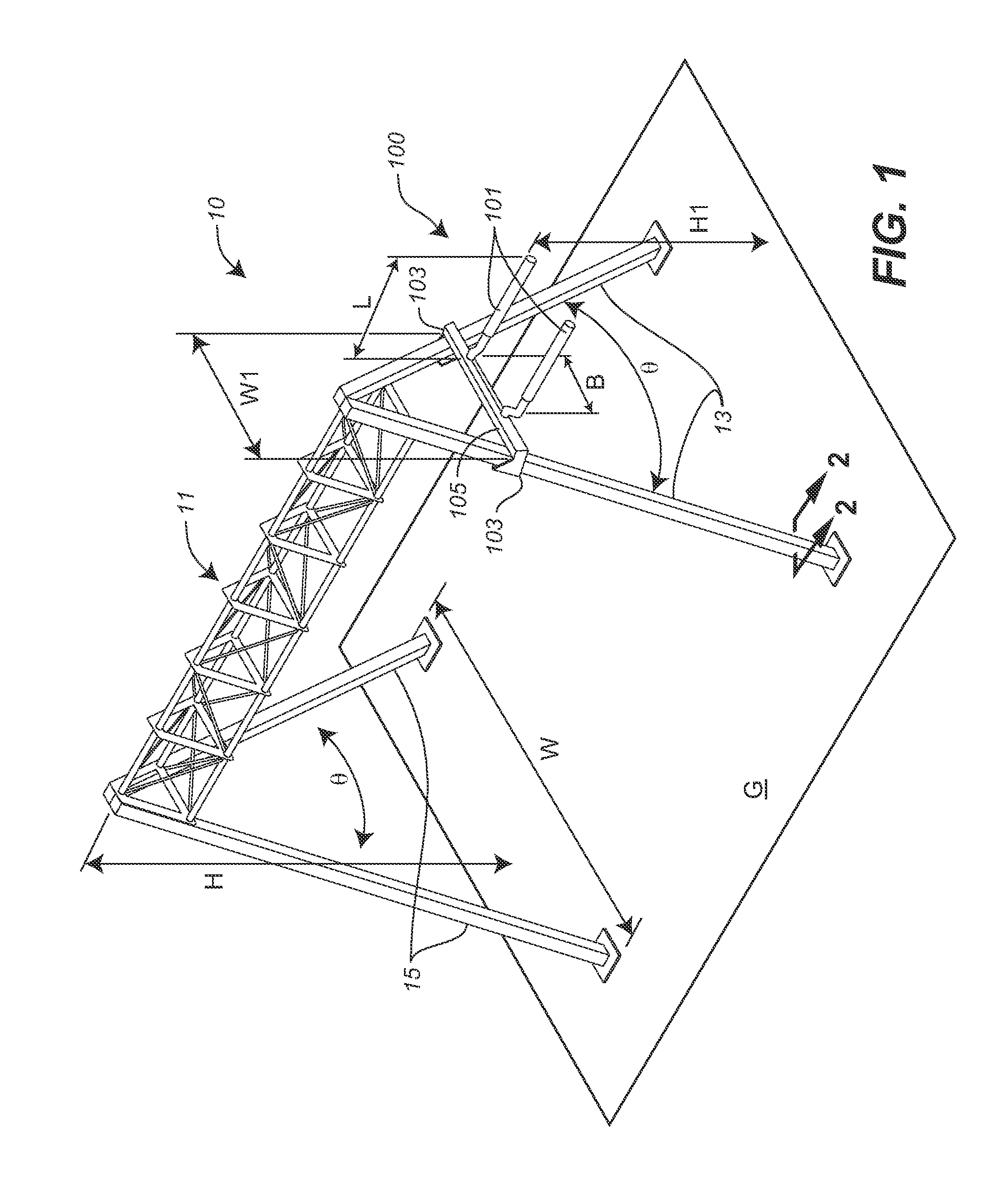
[0024]FIG. 1 is a perspective view of a first embodiment exercise bar attachment 100 supported on a frame 10. In one embodiment, exercise bar attachment 100 includes a pair of bars 101 that may support a user in performing an exercise. While frame 10 is not specifically or necessarily a part of the present invention, the scope of which is to be found in the Claims, frame 10 provides support for frame attachment 100, and thus the following description is provided to illustrate the use exercise bar attachment 100.

[0025]For illustrative purposes, frame 10 is shown in FIG. 1 as including two pairs of members 13 and 15 that support a header 11 a height H above ground G. Members 13 and 15 are shown as being joined at header 11 with an included angle Θ extending to a separation width W on ground G. Each pair of members 13 and members 15 are co-planar and non-parallel, and form the legs of an “A-frame” on ground G. Members 13 and / or 15 may also have additional horizontal pieces, not shown, ...

third embodiment

[0037]FIG. 9 is a perspective view a third embodiment exercise bar attachment 900. While exercise bar attachment 900 may be mounted on frame 10, it may, alternatively, be mounted on a pair of members 901, having the same cross-sectional dimensions and included angle as members 13, may be mounted on a wall W, as shown in FIG. 9. Exercise bar attachment 900 may be generally similar to exercise bar attachment 100 or 300, except as further detailed below. Where possible, similar elements are identified with identical reference numerals in the depiction of the embodiments of FIGS. 1 through 9.

[0038]Third embodiment exercise bar attachment 900 is generally similar to embodiment exercise bar attachments 100 or 300, except that brackets 103 of the second embodiment exercise bar attachment have a spacing W2 which is larger that spacing W1 of the first embodiment exercise bar attachment.

[0039]The larger spacing permits exercise bar attachment 900 to be located at a different height above grou...


PUM

PropertyMeasurementUnit
included angleaaaaaaaaaa
angleaaaaaaaaaa

Abstract

A device and method is described that can easily provide removable exercise bars from the angled portions of a structure and provide a pair of approximately horizontal bars for exercising. The method includes placing an attachment device having a pair of brackets onto co-planar and non-parallel support members. The attachment device brackets include opening for placing, removing, and securing the attachment to the support members. The height of the bars is provided according to the spacing the brackets and the support members.

Description

CROSS-REFERENCE TO RELATED APPLICATIONS[0001]This application claims the benefit of U.S. Provisional Application No. 61 / 418,819, filed Dec. 1, 2010, the entire contents of which are hereby incorporated by reference herein and made part of this specification.BACKGROUND OF THE INVENTION[0002]1. Field of the Invention[0003]The present invention generally relates to exercise equipment, and more particularly to a device including exercise bars that are removably attachable to a frame or structure.[0004]2. Discussion of the Background[0005]Gymnasiums are typically used for a number of exercises, each possibly requiring different equipment and / or configurations of equipment. Since flexibility of the workout space is important, users either have to reconfigure equipment or work with what is available.[0006]While there are some devices which allow for reconfiguring equipment, the mounting, assembly, or reconfiguration exercise space is not, in general, easily done. Specifically, there is no ...

Claims


Application Information

Patent Timeline
Patent Type & Authority Applications(United States)
IPC IPC(8): A63B26/00B23P11/00
CPCA63B2208/029A63B23/1218A63B17/04Y10T29/49826A63B9/00A63B3/00A63B23/1227A63B1/00A63B23/0216A63B71/023A63B21/00047
Inventor HETRICK, RANDALRUSSO, STEPHANIE
Owner JFXD TRX ACQ LLC
Why Eureka
Try Eureka