
Fighting trainer

a trainer and trainer technology, applied in the field of fighter trainers, can solve the problems of longer time to restore uncontrollable balls, and bouncing back the filling sack to hit and hurt the user, and achieve the effect of less oscillation amplitude, rapid bouncing back the ball, and reducing the amplitude of oscillation

Inactive Publication Date: 2012-06-14
FU DICKSON +1
View PDF10 Cites 12 Cited by
  • Summary
  • Abstract
  • Description
  • Claims
  • Application Information

AI Technical Summary

Benefits of technology

[0007]Unlike the defects listed above, the present invention provides the a fighting trainer with a less oscillating amplitude and resilience to meet various requirements. The oscillation can be minimized to rapidly bounce back the ball to meet the training requirement of certain fighting items; the overall strength is therefore sufficient to solve the torsion.
[0009]The resilience adjustment set comprises a first tube, a second tube and a resilient pole, or a tube and a resilient pole. The resilient pole is connected to the base by one end and to the main body or the receiving element by the other end. The resilient pole further comprises a first connecting portion, a second connecting portion, a first pole, a second pole, and a resilient portion. The length of the hollow tube between the first tube and the second tube can adjust the length of the resilient pole or lengthen the resilience adjustment set in order to change the elasticity of the resilient pole. The base has a joining portion at the upper portion. Bowl or plate shape is formed at the lower portion of the receiving set and a bearing is positioned at the inner bottom side.
[0010]Preferably, the resilient portion can be selected from a group comprising a metallic spring or a plastic resilient element. The plastic resilient element can be made of rubber, thermoplastic rubber (TPR) or thermoplastic elastomer (TPE). The bearing is a thrust bearing or a circular bowl structure. The resilience adjustment set and the base has a bar connected therein. The bar has an upper distal end connected to the lower primal end of the resilience adjustment set. As the lower distal end of the bar is connected to the joining portion of the base, the height of the fighting trainer can be adjusted according to the requirement. As the length of the first tube and the second tube is different, regardless of the resilient element being positioned upwards or downward offers various oscillations for the main body. The base can add at least one extra weighing object in the inner portion of the base or above. A spinner can be set between the resilient element and the base; the upper end of the spinner is connected to the lower end of the resilience adjustment set, and the lower end of the spinner is connected to the joining portion of the base. The main body and the connecting base can be assembled as a set or as one-piece. The resilience adjustment set can coordinate with the spinner to release the elastic strength to prevent from falling upon receiving force caused by gravity.

Problems solved by technology

The resilience of the resilient element in the fighting trainer is fixed and cannot be adjusted according to various requirements; the amplitude of oscillation of the speed ball is uncontrollable, and excessive force can easily bounce the filling sack back to hit and hurt the user.
Furthermore, the over amplitude of oscillation takes longer time to restore and not suitable for fight trainer.

Method used


Image

  • Fighting trainer
  • Fighting trainer
  • Fighting trainer

Examples


first embodiment

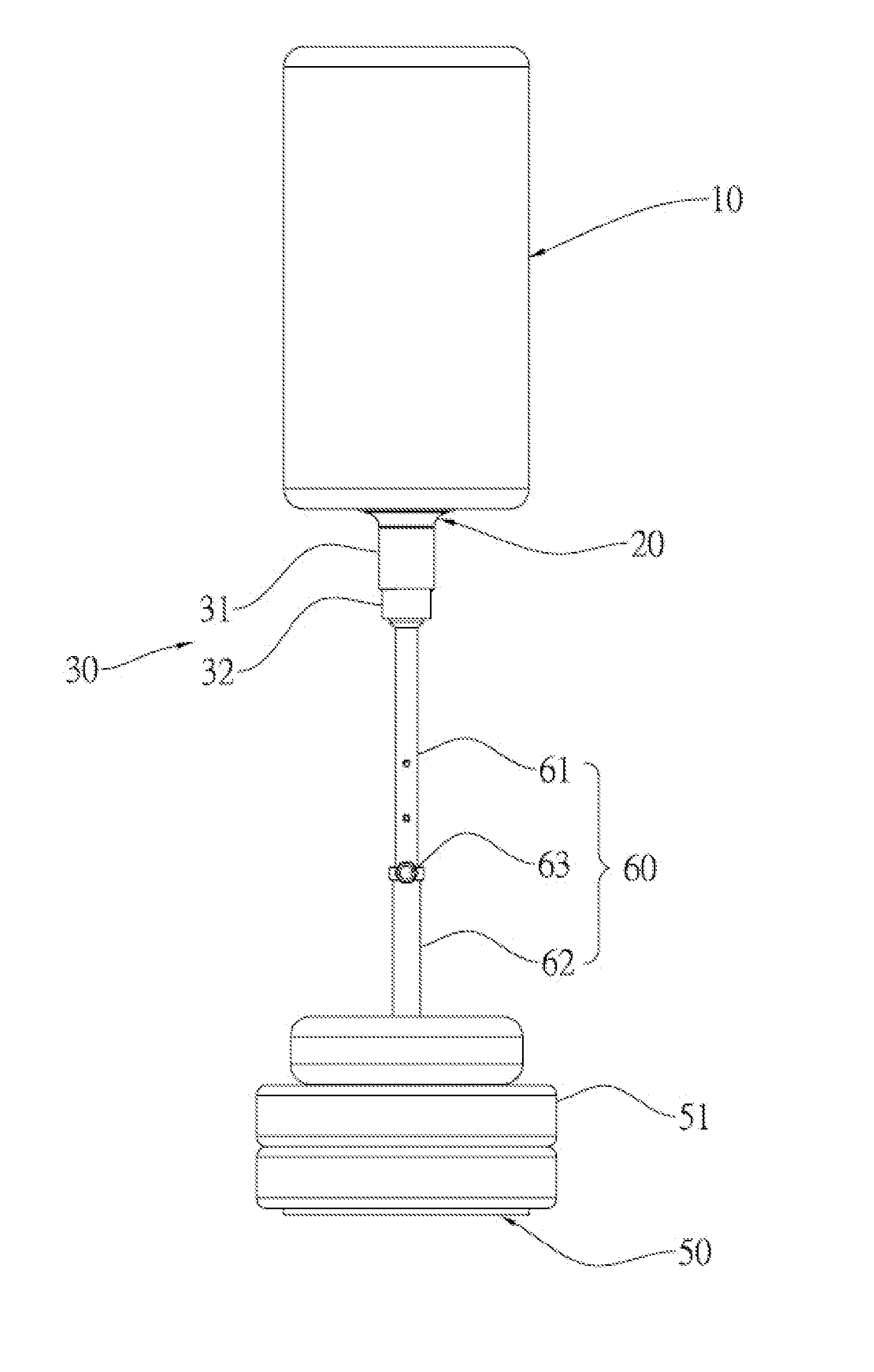
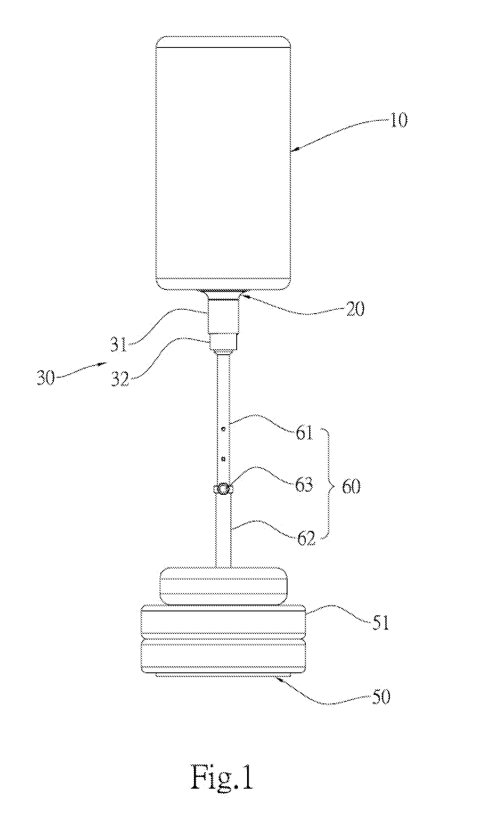
[0027]FIG. 1 illustrates an aspect according to the present invention, which comprises a main body 10, a connecting element 20, a resilience adjustment set 30, a base 50, and a connecting bar 60.

[0028]The resilience adjustment set 30 comprises a first tube 31, a second tube 32, and a spring set positioned within. The base 50 has at least one extra weighing object 51. The connecting bar 60 comprises a first connecting bar 61, a second connecting bar 62, and a securing portion 63.

[0029]The lower portion of the main body 10 is connected to the upper portion of the connecting element 20. The lower portion of the connecting element 20 is connected to the upper portion of the resilience adjustment set 30, and the resilience adjustment set 30 comprises a first tube 31 connected to upper end of the second tube 32 by the lower portion. The resilience adjustment set 30 has the lower end connected to a distal end of the first bar 61 of the connecting bar 60. The other end of the first connecti...

second embodiment

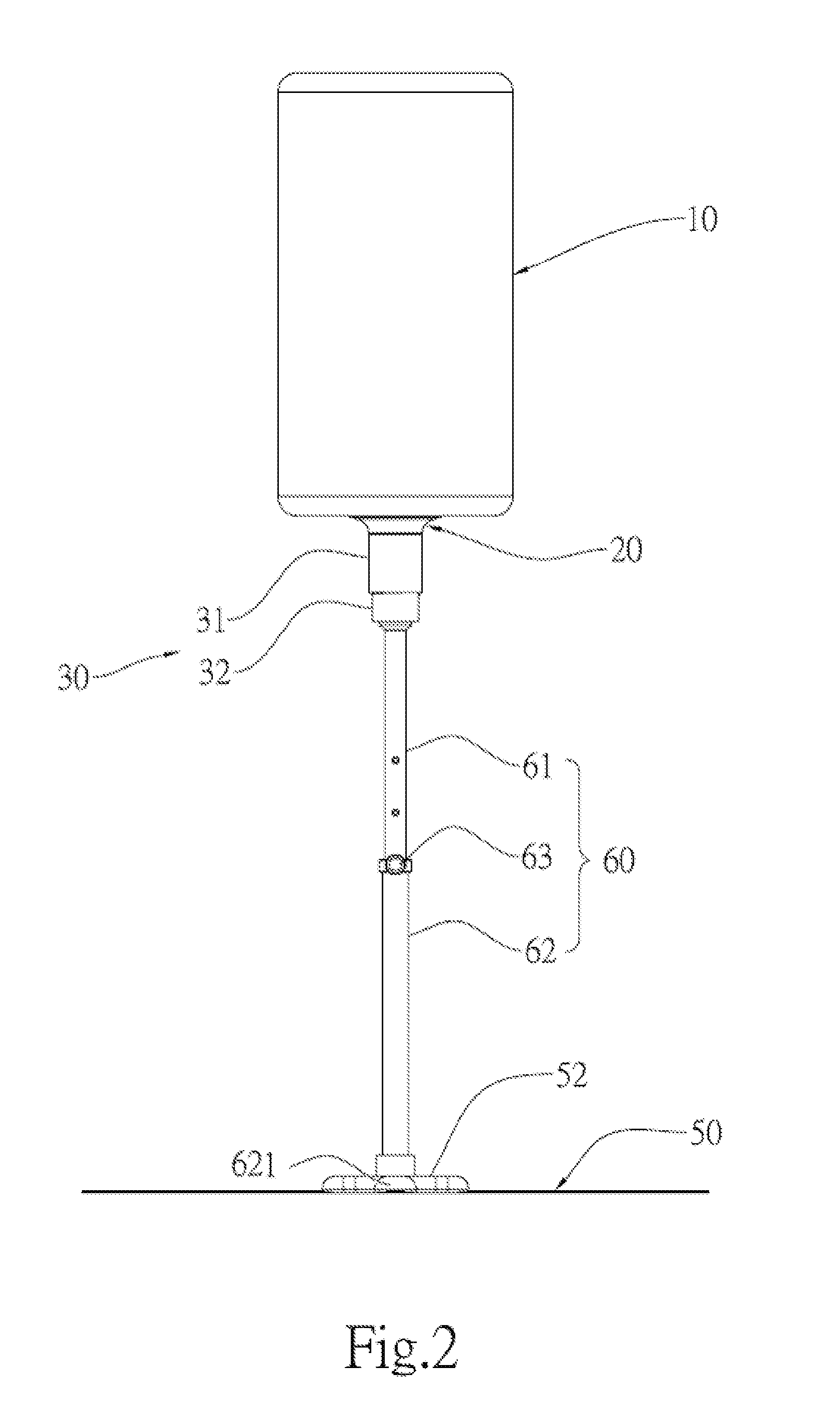
[0031]FIG. 2 is an aspect according to the present invention, which comprises a main body 10, a connecting element 20, a resilience adjustment set 30, a base 50, and a connecting bar 60.

[0032]The resilience adjustment set 30 comprises a first tube 31, a second tube 32, and a spring set. The base 50 has a joining portion 52 above thereof. The connecting bar 60 comprises a first connecting bar 61, a second connecting bar 62, and a securing portion 63. The base 50 may be securely screwed to the ground with a joining portion 52 above thereof.

[0033]The lower portion of the main body 10 penetrates through the connecting element 20 and assembles to the upper portion of the resilience adjustment set 30. The lower portion of the first tube 31 of the resilience adjustment set 30 is connected to the upper portion of the second tube 32. The lower portion of the resilience adjustment set 30 is connected to the distal end of the first connecting bar 61 of the connecting bar 60, and the other end ...

third embodiment

[0034]FIG. 3 is an aspect according to the present invention, which comprises a main body 10, a connecting element 20, a resilience adjustment set 30, a base 50, and a connecting bar 60.

[0035]The resilience adjustment set 30 comprises a first tube 31, a second tube 32, and a spring set. The base 50 has at least one weighing object above. The connecting bar 60 comprises a first connecting bar 61, a second connecting bar 62, and a securing portion 63.

[0036]The assembly of the main 10, the connecting element 20, the resilience adjustment set 30, and the connecting bar 60 is shown in FIG. 2. The other end of the second bar 62 of is connected to the upper end covered by the guarding on the base 50.

[0037]The elasticity of the resilience adjustment set 30 and the amplitude of oscillation of the main body 10 can be adjusted, as shown in FIG. 1.

[0038]FIG. 4 is an aspect according to the forth embodiment of the present invention, which comprises a main body 10, a connecting element 20, a resi...


PUM


Abstract

The present invention relates to a fighting trainer with a hinderer amplitude of oscillation and resilience, comprising a main body, a connecting element, a resilience adjustment set, and a base. By adjusting the distance between the tubes of the resilience adjustment set and the elasticity, the present invention is able to meet various requirements, as well as minimizing the amplitude of oscillation in order to reduce the required space to exercise.

Description

BACKGROUND OF THE INVENTION[0001]1. Field of the Invention[0002]The present invention relates to a fighting trainer which reduces the amplitude of oscillation and the resilience.[0003]2. Description of Related Art[0004]The conventional fighting trainer is based on force acceptance. For example, a speed ball or filling sack for receiving punches, the resilient element attached to the force acceptance, which enables the force acceptance to swing back and forth to perform as a fighting trainer.[0005]The resilience of the resilient element in the fighting trainer is fixed and cannot be adjusted according to various requirements; the amplitude of oscillation of the speed ball is uncontrollable, and excessive force can easily bounce the filling sack back to hit and hurt the user. Furthermore, the over amplitude of oscillation takes longer time to restore and not suitable for fight trainer.[0006]Therefore, the fighting trainer still has room for improvement.SUMMARY OF THE INVENTION[0007]Un...

Claims


Application Information

Patent Timeline
Patent Type & Authority Applications(United States)
IPC IPC(8): A63B69/24
CPCA63B63/06A63B69/004A63B2225/093A63B2071/026A63B69/201A63B69/305A63B2244/10A63B69/22
Inventor FU, DICKSONFU, DAVID
Owner FU DICKSON
Learn More