Floor Register With Rotatable Air Deflector

Inactive Publication Date: 2012-06-21
DESOUZA RICHARD
View PDF2 Cites 7 Cited by
  • Summary
  • Abstract
  • Description
  • Claims
  • Application Information

AI Technical Summary

Benefits of technology

[0010]The deflector in the extended position may de

Problems solved by technology

The prior art air deflectors are either rigidly affixed to the air register, or are removable, but cannot be adjusted easily.
A fixed air register is by definition not easily adjustable, and a removable air register must be stored and replaced each time the air flow is adjusted.

Method used


Image

  • Floor Register With Rotatable Air Deflector
  • Floor Register With Rotatable Air Deflector
  • Floor Register With Rotatable Air Deflector

Examples


Embodiment Construction

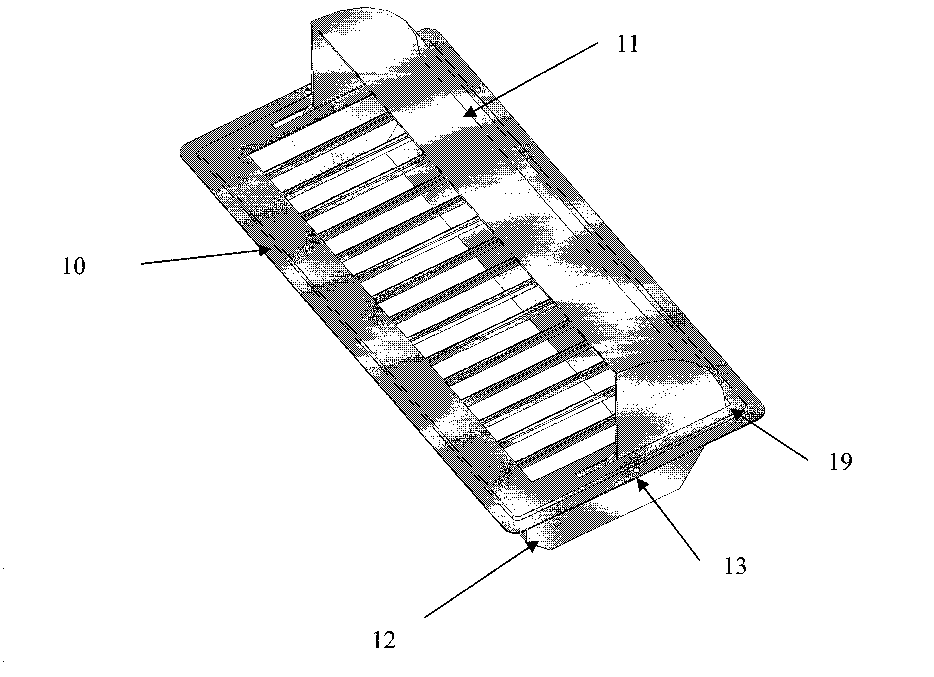
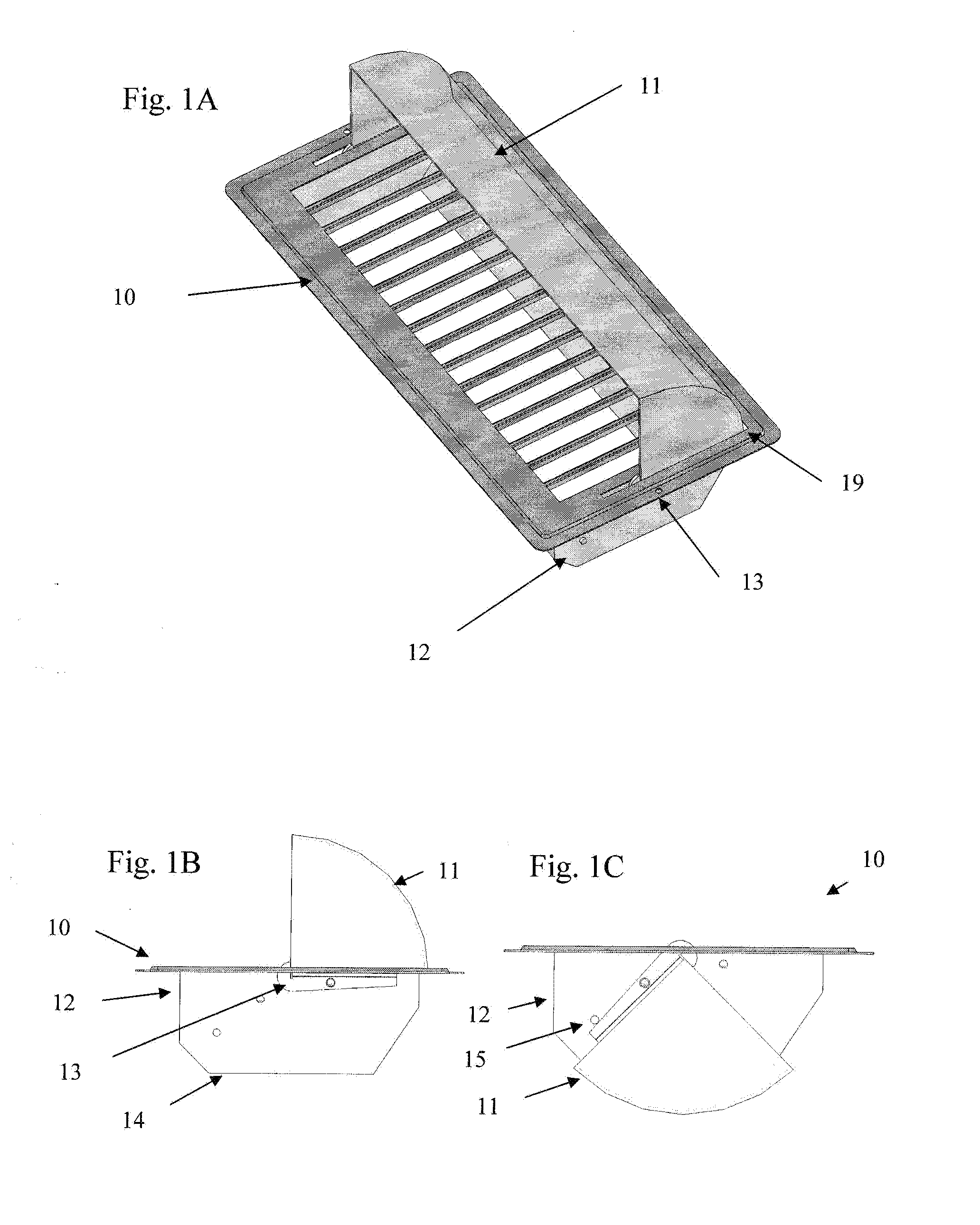
[0023]FIGS. 1A and 1C show a first embodiment of the invention which may include a grill 10 affixed to a damper box 12 to form an air register for an air vent.

[0024]The damper box 12 may define a passage through which air may flow. One end of the passage may open to the grill 10, and the second end of the passage 14 may be in fluid communication with an air duct. The damper box may preferably be a rectangular prism may have a tapered portion at the second end 14, but may be any shape that performs its function.

[0025]The grill 10 may define a plurality of openings which allow the passage of air. The grill 10 may also have a flange which extends outwardly around the edge of the grill 10 to rest upon any adjacent surface, but this flange may not be necessary for certain applications. In this preferred embodiment, the flange may include holes to permit a fastener, such as a screw, to be used to affix the air register to the air duct or adjacent surface.

[0026]The grill 10 is shown with a...


PUM


Abstract

An air register for covering an air duct opening in a space ventilated by a forced central air system. The invention permits the user to change the direction of the air flow by rotating the air deflector. The invention also permits the user to regulate the amount of the air flowing into the space by adjusting the shutter of the damper box, by rotating the air deflector, or by doing both. The invention therefore gives the user many options in selecting the desirable air flow setting.

Description

PRIORITY[0001]The present invention claims priority under 35 USC section 119 based upon a provisional application which was filed on Dec. 4, 2009 and which has a Ser. No. of 61 / 266,542.FIELD OF THE INVENTION[0002]The present invention relates generally to air registers for regulation the flow of air from a heating or air-conditioning system.BACKGROUND OF THE INVENTION[0003]For a space that is ventilated by a forced central air system, air registers are used to cover air duct opening on walls, ceilings, and / or floors of the space. They allow air to flow into the space while preventing large objects from entering the duct.[0004]Air registers typically consists of two parts: the grill, which is the outside part of the register used mainly to cover the opening, and the damper box, which is the inside part of the register used to control the air flow through the duct. The damper box is sized to fit within an air duct opening. The grill cover is typically designed with parallel louvers, b...

Claims


Application Information

Patent Timeline
IPC IPC(8): F24F13/10
CPCF24F13/082F24F13/065
Inventor DESOUZA, RICHARD
Owner DESOUZA RICHARD
Why Eureka
Try Eureka