LED illumination apparatus

Inactive Publication Date: 2012-06-28
HONG FU JIN PRECISION IND (SHENZHEN) CO LTD +1
View PDF5 Cites 1 Cited by
  • Summary
  • Abstract
  • Description
  • Claims
  • Application Information

AI Technical Summary

Problems solved by technology

However, characteristics of each LED are different from each other and may cause the current in each branch to be different.
The current provided to each branch of the LED series-parallel connection circuit is not constant, which may decrease service life of the LEDs.

Method used


Image

  • LED illumination apparatus
  • LED illumination apparatus
  • LED illumination apparatus

Examples


Embodiment Construction

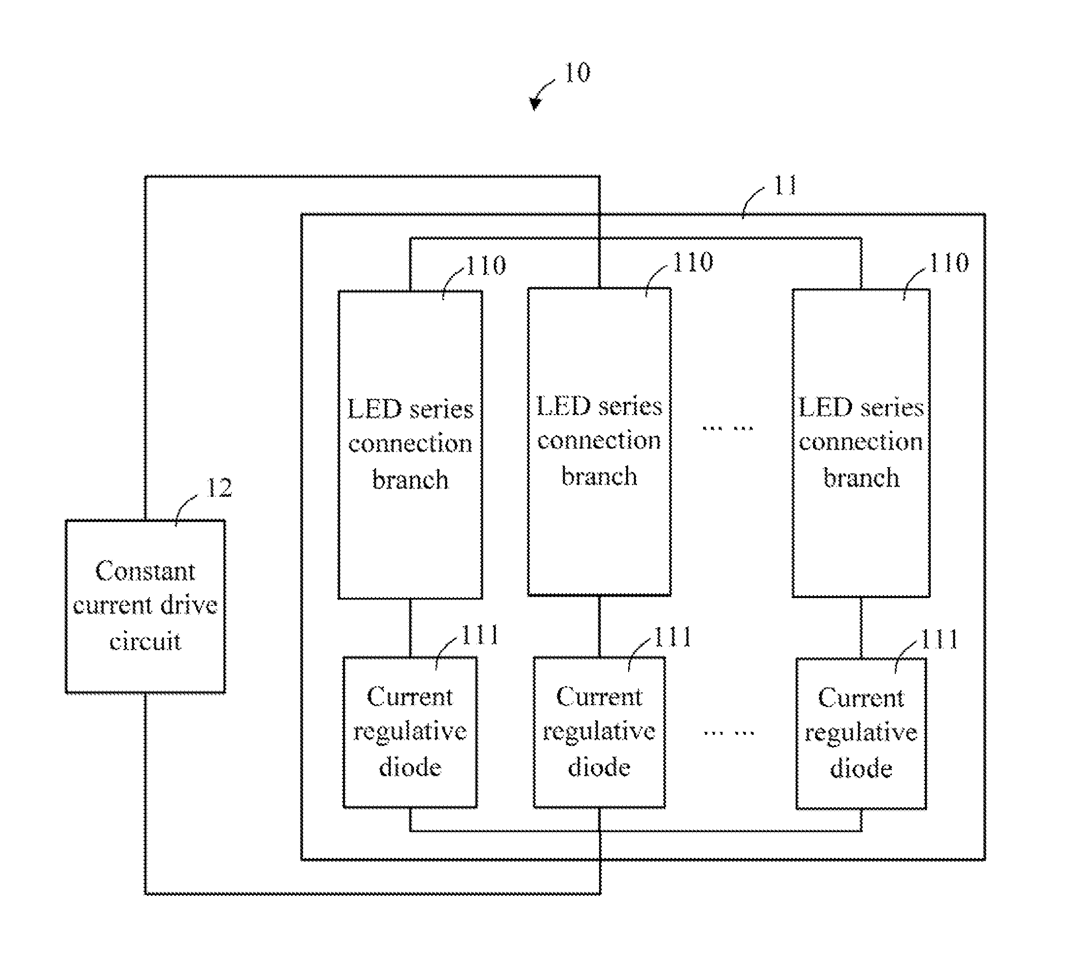
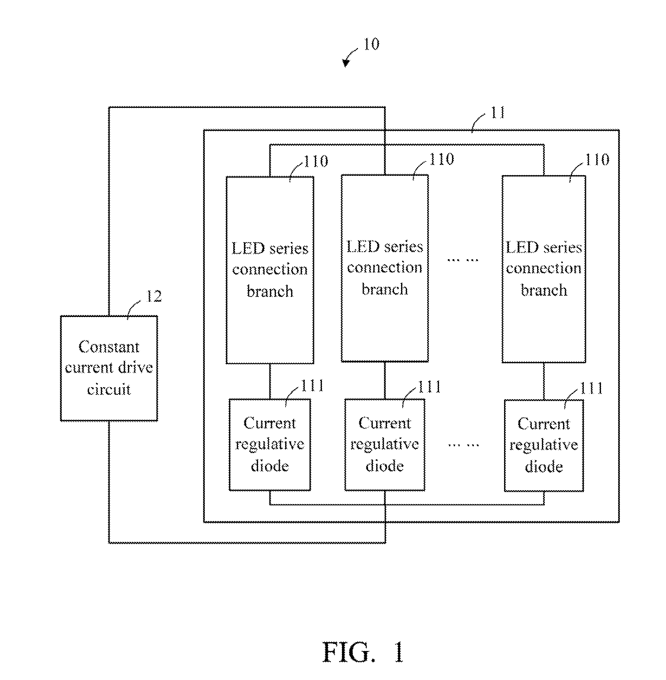
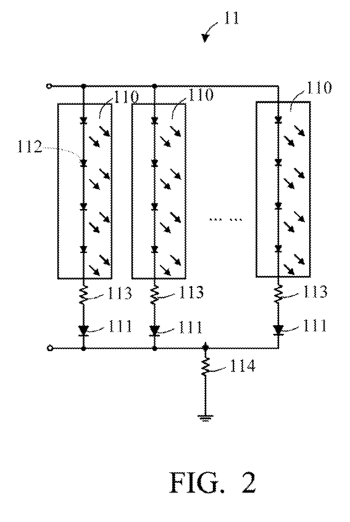
[0010]Referring to FIGS. 1 and 2, an LED illumination apparatus 10 includes an LED illumination circuit 11 and a constant current drive circuit 12 for driving the LED illumination circuit 11. The illumination LED circuit 11 includes at least two lighting branches 110; each of the lighting branches 110 includes a number of LEDs 112 and a current regulative diode 111 connected in series.

[0011]The LEDs 112 are connected in series. In the embodiment, the last LED 112 is connected to the anode of the current regulative diode 111 via a resistor 113. The cathodes of the current regulative diodes 111 are grounded via a resistor 114.

[0012]Referring to FIG. 3, in an alternative embodiment, in each lighting branch 110, the current regulative diodes 111 are connected between the last LED 112 and the resistor 113.

[0013]The current regulative diodes 111 are provided to maintain the current flowing therethrough being constant. When the current provided by the constant current drive circuit 12 chan...


PUM


Abstract

A light emitting diode (LED) illumination apparatus includes an LED illumination circuit and a constant current drive circuit to provide constant current to the LED illumination circuit. The LED illumination circuit includes at least two lighting branches connected in parallel, and each of the at least two lighting branches includes at least one LED and a current regulative diode connected in series.

Description

BACKGROUND[0001]1. Technical Field[0002]The present disclosure relates to LED illumination apparatuses, and particularly, to an LED illumination apparatus with an LED illumination circuit thereof.[0003]2. Description of the Related Art[0004]An LED illumination apparatus commonly includes an LED series-parallel connection circuit with a number of LEDs, and a constant-current drive circuit for driving the LEDs using a constant current. However, characteristics of each LED are different from each other and may cause the current in each branch to be different. Furthermore, the constant-current drive circuit usually can maintain the stability of the current of the main circuit, but not for each branch. The current provided to each branch of the LED series-parallel connection circuit is not constant, which may decrease service life of the LEDs.[0005]Therefore, there is room for improvement within the art.BRIEF DESCRIPTION OF THE DRAWINGS[0006]The components in the drawings are not necessa...

Claims


Application Information

Patent Timeline
IPC IPC(8): H05B37/02
CPCH05B45/40
Inventor CHI, DER-HOCHAO, YANG-JUIXIE, ZHI-QIANGFU, JI-BAOTANG, MIWU, WEN-TAO
Owner HONG FU JIN PRECISION IND (SHENZHEN) CO LTD
Why Eureka
Try Eureka