Ionizer and electrostatic charge eliminating system

a technology of electrostatic charge and ionizer, which is applied in the direction of electrostatic charge, corona discharge, basic electric elements, etc., can solve the problem of further increasing the total electric current consumption of simultaneously operating all the ionizers, and achieve the effect of not increasing the current consumption

Inactive Publication Date: 2012-06-28
DESCO IND
View PDF8 Cites 3 Cited by
  • Summary
  • Abstract
  • Description
  • Claims
  • Application Information

AI Technical Summary

Benefits of technology

[0008]According to the ionizer and the electrostatic charge eliminating system of the present invention, when the timing of operating the optional function is shifted, it is possible to operate the optional function without increasing the current consumption. Due to the foregoing, it is possible to simultaneously use a plurality of ionizers having an optional function such as a cleaning function. Further, it is possible to use an electrostatic charge eliminating device having a plurality of optional functions.

Problems solved by technology

Accordingly, a total electric current consumption for simultaneously operating all the ionizers is further increased.

Method used


Image

  • Ionizer and electrostatic charge eliminating system
  • Ionizer and electrostatic charge eliminating system
  • Ionizer and electrostatic charge eliminating system

Examples


first embodiment

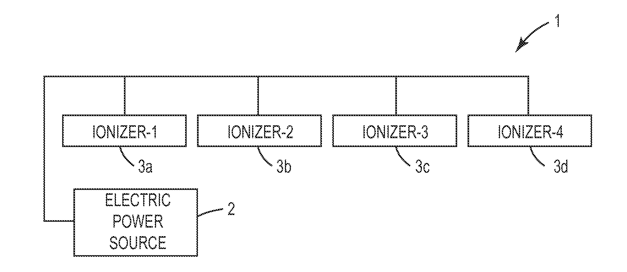
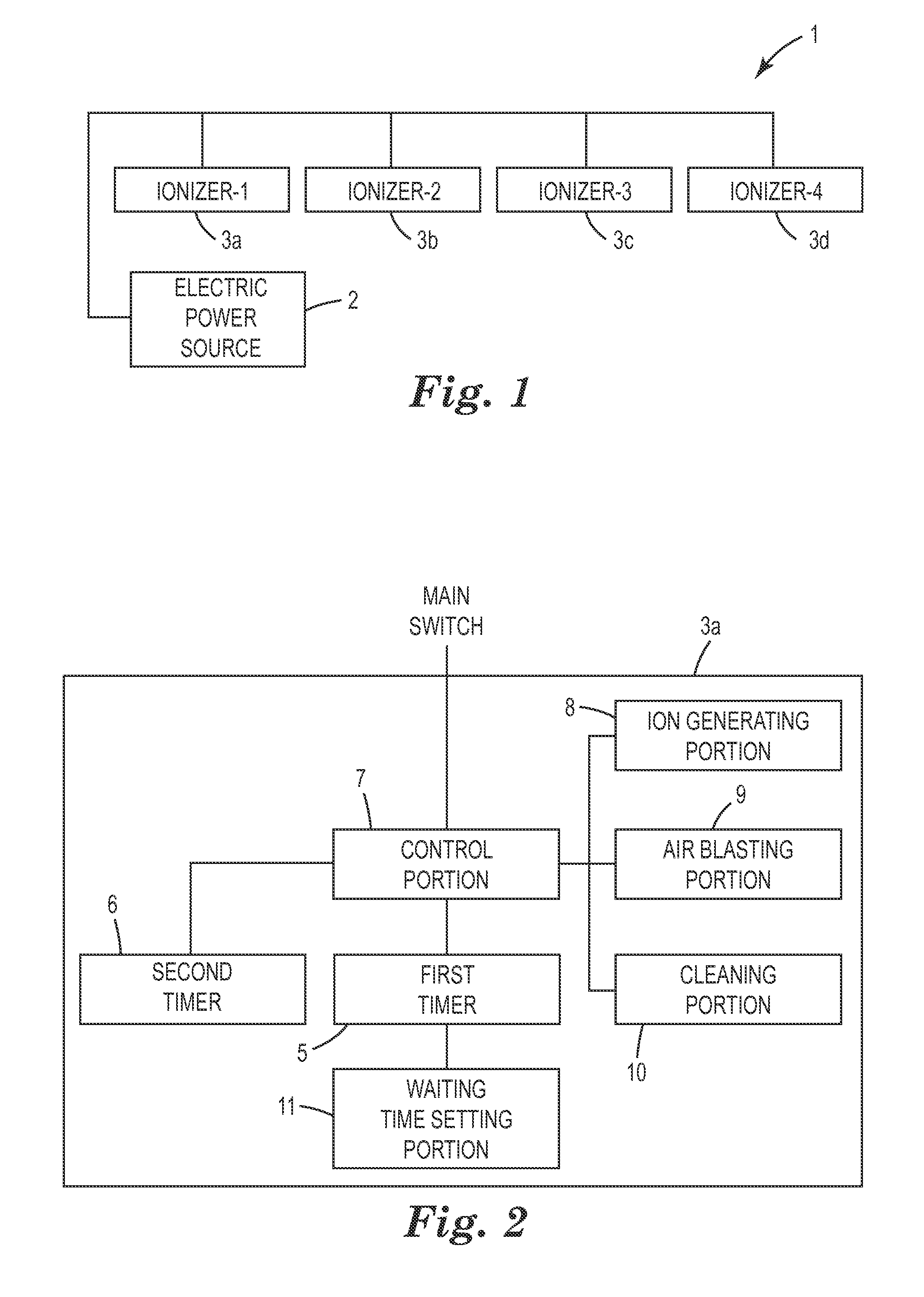
[0027]Referring to the drawings, an embodiment of the ionizer and the electrostatic charge eliminating system of the present invention will be explained below. FIG. 1 shows an ionizer and an electrostatic charge eliminating system of the present invention. As shown in the drawing, although electrostatic charge eliminating system 1 of the present embodiment is not restricted by this embodiment, for example, electrostatic charge eliminating system 1 of the present embodiment can be applied to an IC handler of a semiconductor manufacturing system in a clean room. Electrostatic charge eliminating system 1 includes a plurality of ionizers 3a to 3d. Ionizers 3a-3d are connected to electric power source 2 (for example, DC electric power source) in parallel. Further, electric power source 2 is electrically connected to an IC handler and various devices so that electric power can be supplied. An allowable current of electric power source 2 is decided at a predetermined ampere. Therefore, in ...

second embodiment

[0038]Next, the ionizer and the electrostatic charge eliminating system of second embodiment will be explained below. As shown in FIG. 7, the electrostatic charge eliminating system of the present embodiment includes: electric power source 2; and ionizers 23a to 23d. As shown in FIG. 8, each ionizer 23a to 23d includes: second timer 6; first timer 5 for setting waiting time t1 by random circuit 11; and third timer 28 for measuring waiting time t3 to a time at which a voltage level of common signal line 24 is detected when other ionizer 23a to 23d is executing the cleaning operation. Each ionizer 23a to 23d of the present embodiment includes: signal detecting portion 25 connected to common signal operation line 24 and detecting a voltage level of common operation signal line 24; and signal output portion 26 for outputting an operation signal to common operation signal line 24 so that a voltage level of common operation signal line 24 can be decreased.

[0039]FIG. 9 is a circuit diagram...

third embodiment

[0044]Next, the ionizer and the electrostatic charge eliminating system of the present invention will be explained below. As shown in FIG. 13, the electrostatic charge eliminating system of the present embodiment includes: electric power source 2; and ionizer 31. Ionizer 31 includes: control unit 32; and a plurality of electrostatic charge eliminating units 33a to 33d connected to control unit 32. Each electrostatic charge eliminating unit 33a to 33d is connected to common electric power source 2. As shown in FIG. 14, control unit 32 includes: control portion 34; first timer 5; second timer 6; and communicating portion 36 for sending and receiving signals from communicating portions 36 of electrostatic charge eliminating units 33a to 33d.

[0045]As shown in FIG. 15 in which electrostatic charge eliminating unit 33a is shown as a representation, each electrostatic charge eliminating unit 33a to 33d includes: ion generating portion 8; air blasting portion 9; cleaning portion 10; and co...


PUM


Abstract

In an embodiment of the present invention, an ionizer and an electrostatic charge eliminating system are provided in which optional functions can be operated without increasing a current consumption when a timing of operating the optional functions is shifted in a case where a plurality of ionizers having optional functions such as a cleaning function are simultaneously used or an ionizer having a plurality of optional functions is used. According to an embodiment of the present invention, an ionizer includes: control portion 7; cleaning portion 10 operated when a command is given from control portion 7; first timer 5 for measuring a waiting time from a time at which a power source is turned on to a time at which cleaning portion 10 executes an operation at a first time; and second timer 6 for measuring a cycle time so that cleaning portion 10 can repeatedly execute the operation at a second time or later by a predetermined cycle time.

Description

TECHNICAL FIELD[0001]The present invention relates to an ionizer and an electrostatic charge eliminating system for eliminating an electrostatic charge from an object by neutralizing the electrostatic charge when air ions are blown to the object which is electrically charged with static electricity and from which the electrostatic charge is to be eliminated.BACKGROUND[0002]An example of the ionizer for eliminating an electrostatic charge from an object such as an IC chip or an electronic part having an insulating property is an air blasting type ion generating device described in Official gazette of JP-A-2004-234972. In the paragraph No. 0021 of Official gazette of JP-A-2004-234972, a means for generating air ions is described as follows. “Ion generating means 9 includes: annular opposed electrode 14 attached onto an outer circumference of air ion guide cylinder 12 made of insulating material connected to a front portion of shroud 11; and 8 discharge needles 15 radially arranged at ...

Claims


Application Information

Patent Timeline
Patent Type & Authority Applications(United States)
IPC IPC(8): H05F3/06
CPCH01T23/00H01T19/00
Inventor ITO, MASAHIKOSATO, YOSHIAKI
Owner DESCO IND
Why Eureka
Try Eureka