Strapping force indicator accessory

a technology of strapping force and accessory, which is applied in the field of strapping force indicator accessories, can solve the problems of discomfort, pressure sores and/or open wounds, and unsatisfactory tightening, and achieve the effects of reducing the compliance of therapy, discomfort, and discomfor

Inactive Publication Date: 2012-08-09
KONINKLIJKE PHILIPS ELECTRONICS NV
View PDF7 Cites 29 Cited by
  • Summary
  • Abstract
  • Description
  • Claims
  • Application Information

AI Technical Summary

Problems solved by technology

Over tightening is undesirable as it typically causes discomfort, facial red marks, pressure sores and / or open wounds.
As a result, over tightening can have a tremendously negative effect on compliance with therapy as patients will be reluctant to use the mask as often and / or for as long as directed.
In addition, as mask designs evolve, the amount of strapping force needed to obtain a good seal between the mask and the patient's face often decreases.
However, a patient using such a mask may not know or understand that less strapping force (i.e., than was required for prior mask designs) is needed.
This lack of understanding may lead to over tightening of the headgear used in conjunction with the mask.

Method used


Image

  • Strapping force indicator accessory
  • Strapping force indicator accessory
  • Strapping force indicator accessory

Examples


Embodiment Construction

[0022]Directional phrases used herein, such as, for example and without limitation, top, bottom, left, right, upper, lower, front, back, and derivatives thereof, relate to the orientation of the elements shown in the drawings and are not limiting upon the claims unless expressly recited therein.

[0023]As employed, herein, the statement that two or more parts or components are “coupled” together shall mean that the parts are joined or operate together either directly or through one or more intermediate parts or components. As employed herein, the statement that two or more parts or components “engage” one another shall mean that the parts exert a force against one another either directly or through one or more intermediate parts or components. As employed herein, the term “number” shall mean one or an integer greater than one (i.e., a plurality).

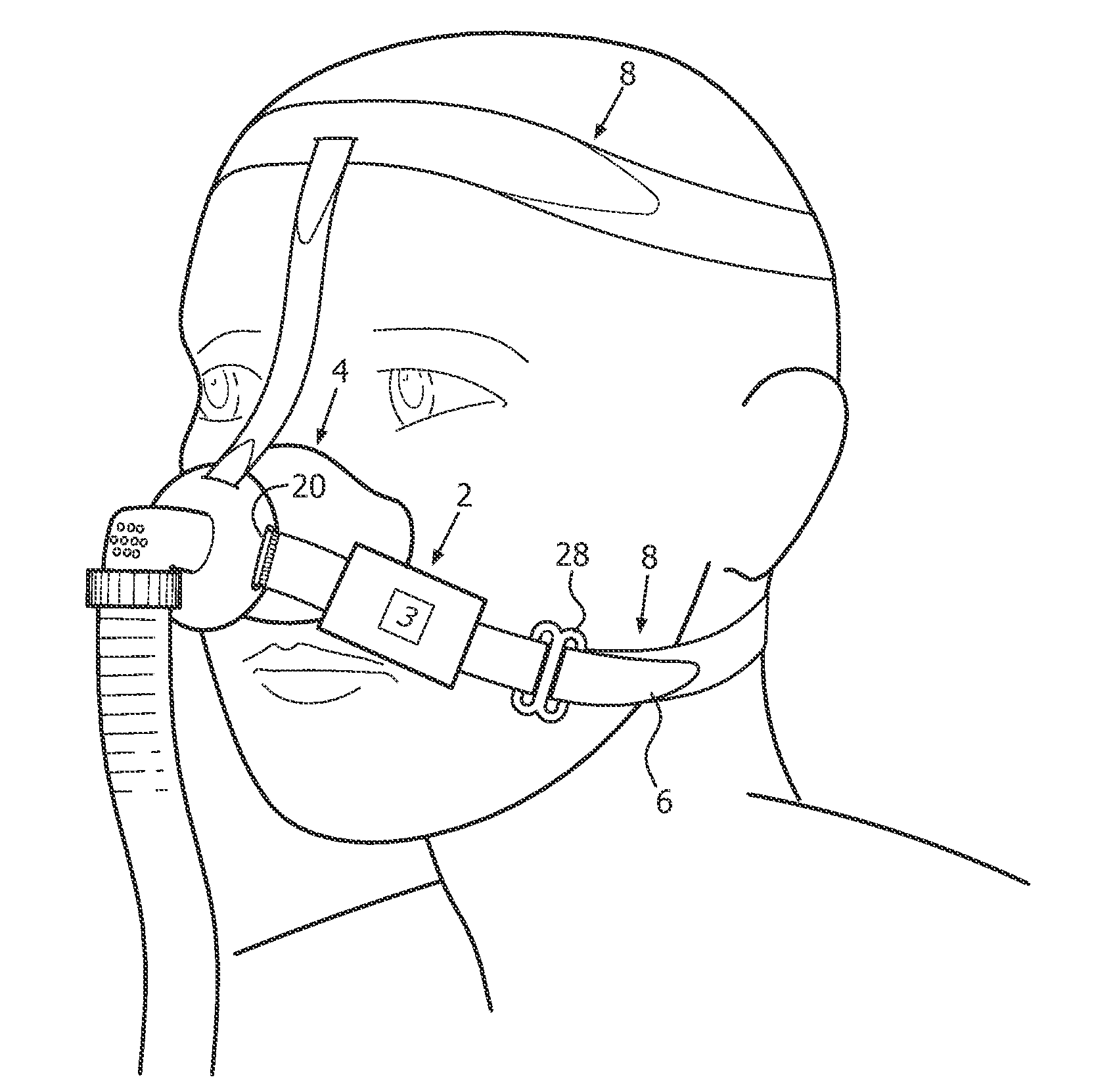
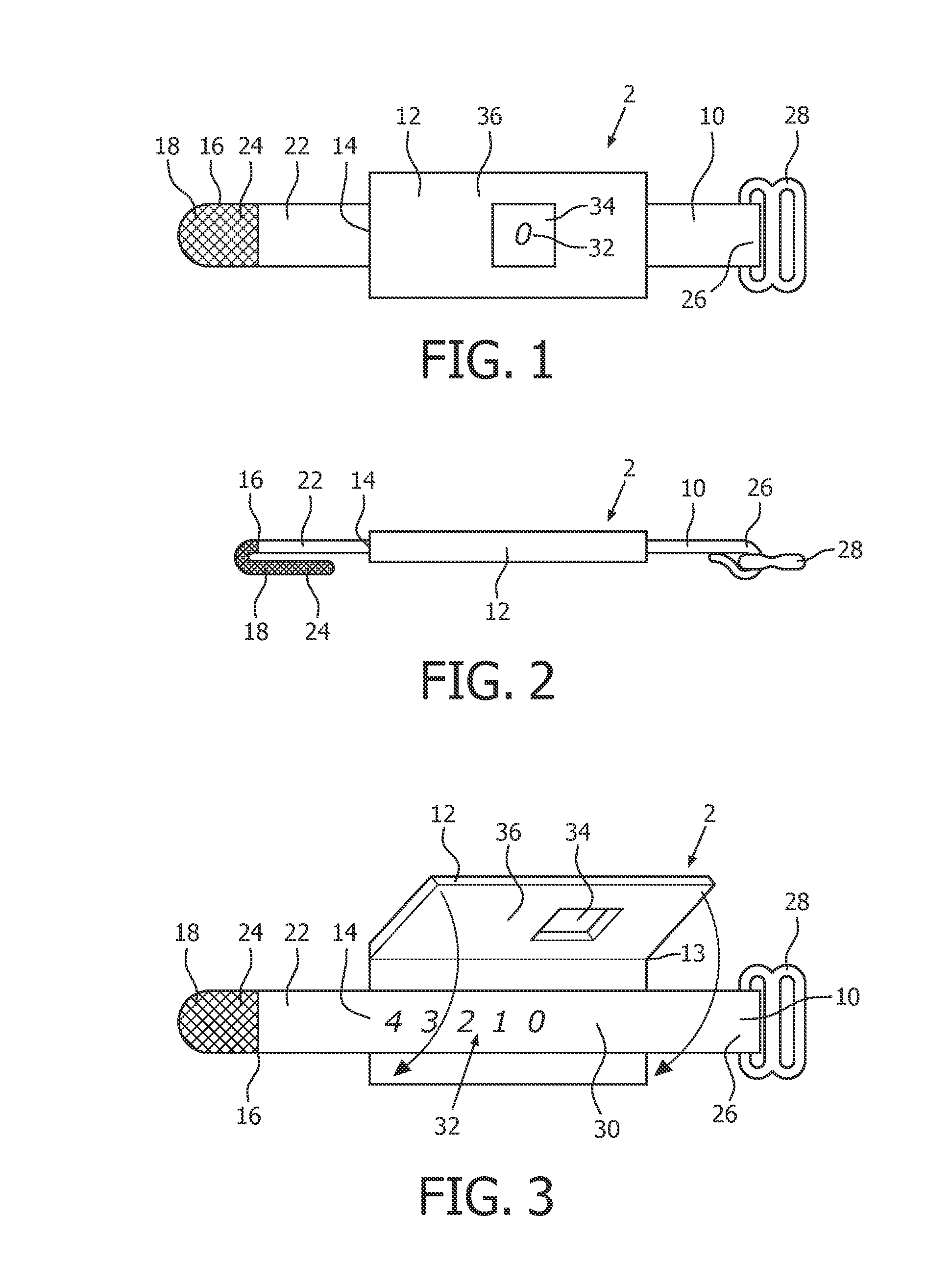
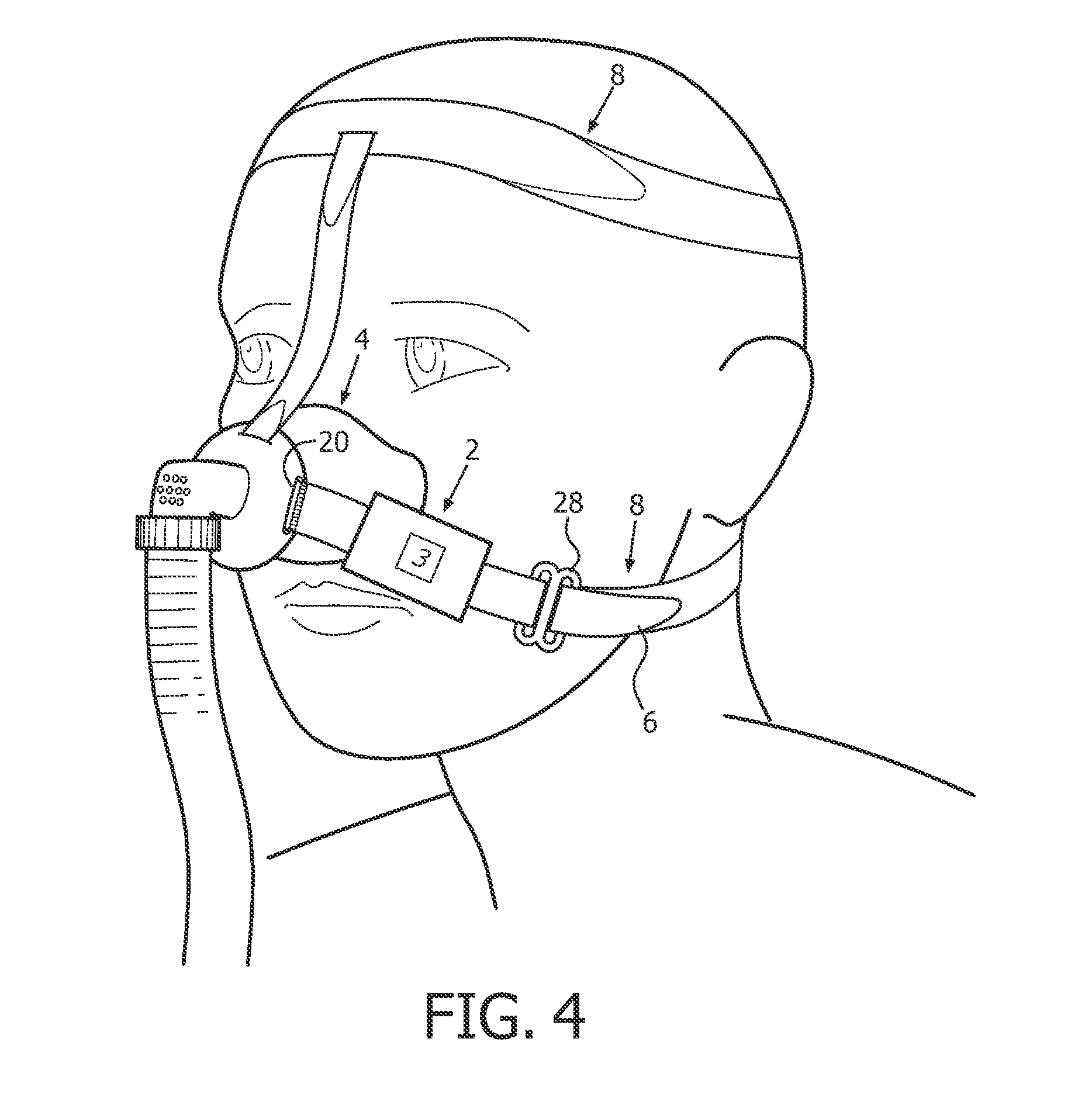
[0024]FIGS. 1 and 2 are top plan and side views, respectively, of strapping force gauging device or accessory 2 according to one embodiment o...


PUM


Abstract

An apparatus for indicating a strapping force applied by a headgear of a patient interface device. The apparatus includes a first portion structured to be selectively connectable to a connecting element of a mask of the patient interface device, a second portion structured to be selectively connectable to a strap of the headgear, and a force gauging mechanism coupled to the first portion and the second portion. The force gauging mechanism is structured to gauge and indicate a force being applied by the headgear in response to the second strap portion being pulled by the strap of the headgear.

Description

CROSS-REFERENCE TO RELATED APPLICATIONS[0001]This patent application claims the priority benefit under 35 U.S.C. §371 of international patent application no. PCT / IB2010 / 054358, filed Sep. 28, 2010, which claims the priority benefit under 35 U.S.C. §119(e) of U.S. Provisional Application No. 61 / 254,264 filed on Oct. 23, 2009, the contents of which are herein incorporated by reference.BACKGROUND OF THE INVENTION[0002]1. Field of the Invention[0003]The present invention relates to patient interface devices for transporting a gas to and / or from an airway of a user, and, in particular, to an accessory for use with a headgear in a patient interface system for gauging and indicating the current strapping force applied by the headgear.[0004]2. Description of the Related Art[0005]There are numerous situations where it is necessary or desirable to deliver a flow of breathing gas non-invasively to the airway of a patient, i.e., without intubating the patient or surgically inserting a tracheal ...

Claims


Application Information

Patent Timeline
Patent Type & Authority Applications(United States)
IPC IPC(8): A61M16/06
CPCA61M16/06G01L5/06A61M2205/583A61M16/0683
Inventor SOFRANKO, RICHARD ANDREWMATULA, JR., JEROMESTARTARE, ANTHONY VINCENTBUSCH, LANCE RANARD
Owner KONINKLIJKE PHILIPS ELECTRONICS NV
Why Eureka
Try Eureka