Optical film and display panel

a technology of optical film and display panel, applied in the field of optical film, can solve the problems of low hardness and abrasion resistance of the low refractive index layer itself, easy damage to the surface low hardness so as to improve the abrasion resistance of reduce the low refractive index layer. , the effect of excellent abrasion resistan

Active Publication Date: 2012-08-09
DAI NIPPON PRINTING CO LTD
View PDF8 Cites 56 Cited by
  • Summary
  • Abstract
  • Description
  • Claims
  • Application Information

AI Technical Summary

Benefits of technology

[0028]Since at least a part of the hollow particles is covered with the cured resin and present in contact with the interface on the side opposite to the optically-transparent substrate side of the low refractive index layer, while ensuring excellent abrasion resistance of the low refractive index layer, the reflectance of the low refractive index layer decreases due to the air contained in the hollow particles. In addition, the dispersion average particle diameter of the solid particles has a value which is a half or less of the thickness d, and the solid particles occupy 50% or more of the interface excluding the part in which the hollow particles are present, and are eccentrically located from the interface to the depth which is twice the dispersion average particle diameter of the solid particles, thereby, the abrasion resistance of the low refractive index layer can be efficiently improved by a small content of solid particles. By taking the above together, an optical film comprising a low refractive index layer excellent in hardness and abrasion resistance as well as adhesion besides having high anti-reflective property, and producible at low cost can be obtained.

Problems solved by technology

In such a low refractive index layer containing hollow particles, the hollow particles are effective for lowering refractive index, however, there are problems that the hardness of the hollow particles is low since the inside of the hollow particles are porous or hollow, thus, the hardness and abrasion resistance of the low refractive index layer itself is low.
Particularly, if the hardness or abrasion resistance is low, the surface of the low refractive index layer is easily damaged when a sharp object contacts the surface, and when the surface is damaged, the visibility of the antireflection film decreases and it leads to the deterioration of the appearance.
However, such an anti-reflection laminate of Patent Literature 1 can have a good anti-reflective property, but has problems such as increase in cost and decrease in adhesion due to increase in the amount of solid particles to be used, since hollow particles and solid particles are uniformly and densely filled in the low refractive index layer.

Method used


Image

  • Optical film and display panel
  • Optical film and display panel
  • Optical film and display panel

Examples


example 1

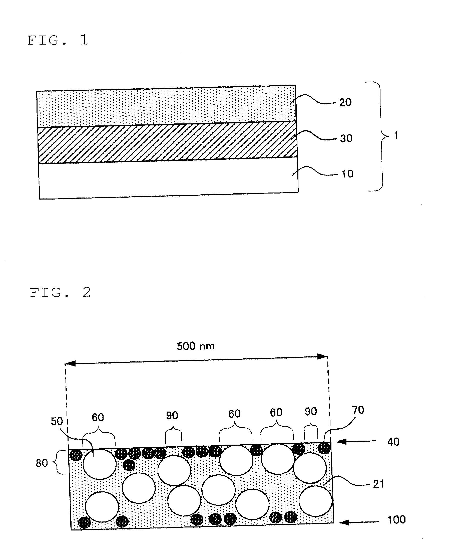
[0304]The curable resin composition for hard coat layer was bar coated on one side of the TAC substrate (TF80UL), dried in a heat oven at 70° C. for 60 seconds to evaporate the solvent in the coating layer. The coating layer was irradiated with ultraviolet having the integral exposure amount of 200 mJ / cm2 under nitrogen atmosphere by means of ultraviolet irradiation device (light source: H Bulb; manufactured by Fusion UV Systems Japan KK), and cured. Thus, a hard coat layer was formed.

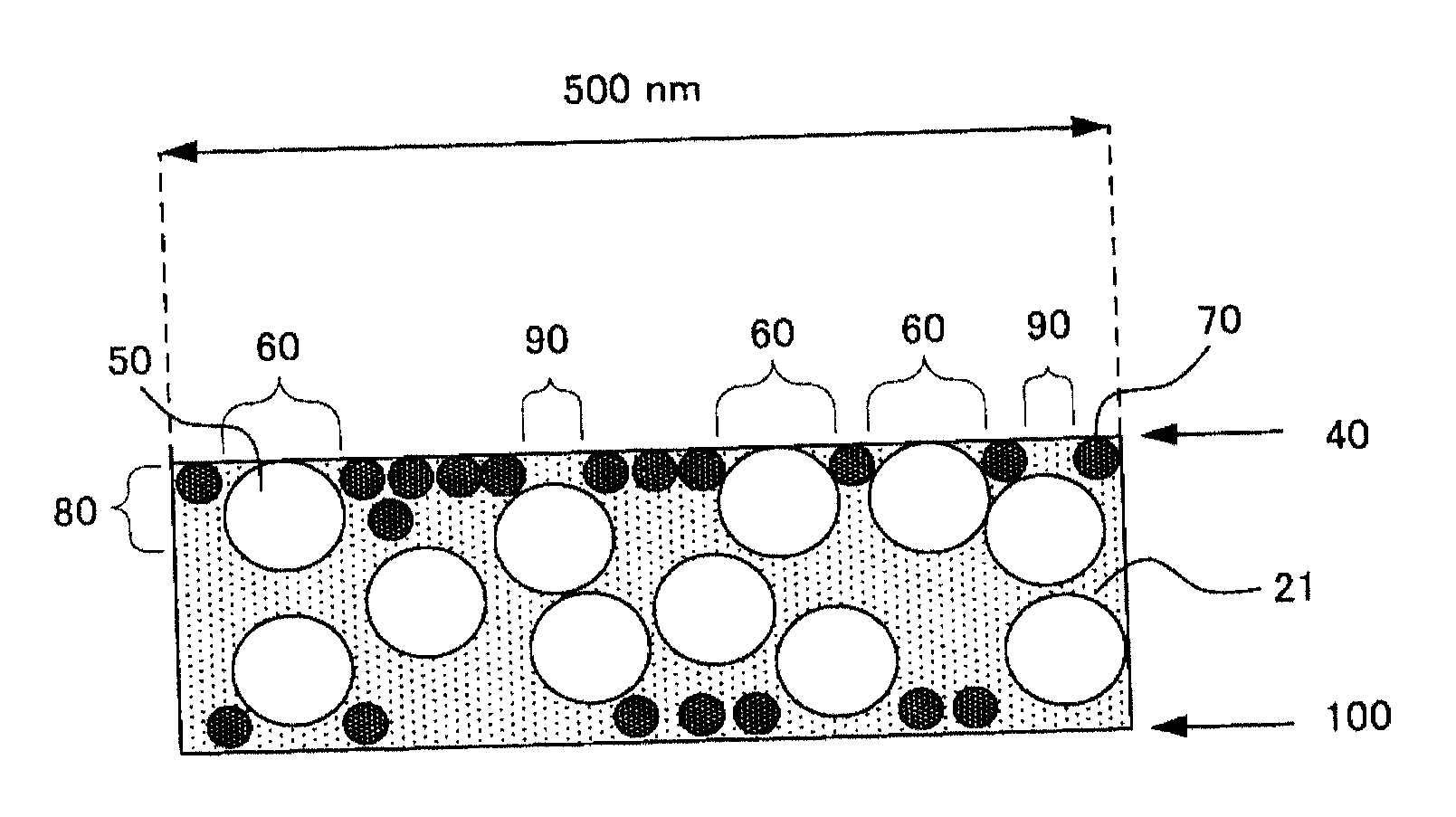
[0305]Next, the curable resin composition 1 for low refractive index layer was bar coated on the hard coat layer, and was subjected to ultraviolet irradiation similarly as the hard coat layer to form a low refractive index layer. Thus, an optical film was obtained.

[0306]The thickness of the low refractive index layer was set so that the minimum of the reflectance measured using a spectrometer (product name: UV-3100PC; manufactured by: Shimadzu Corporation) was present around the wavelength of 550 nm.


PUM

PropertyMeasurementUnit
thicknessaaaaaaaaaa
particle diameteraaaaaaaaaa
widthaaaaaaaaaa

Abstract

An optical film having an optically-transparent substrate, and a low refractive index layer having a thickness d on one side of the optically-transparent substrate, a polarizing plate and a display panel provided with the same, and a display provided with the same.

Description

TECHNICAL FIELD[0001]The present invention relates to an optical film to be disposed on the front face of a display (image display device) of a liquid crystal display (LCD), a cathode tube (CRT) display device, a plasma display (PDP), an organic electroluminescence (organic EL), an electronic paper, etc., a polarizer provided with the optical film, a display panel provided with the optical film or polarizer, and a display provided with the optical film, polarizer or display panel.BACKGROUND ART[0002]It is required for an image display surface of displays of, for example, TVs, PCs, mobile phones, GPS (global positioning system), car navigations, graphics tablets, CAD (Computer aided design system), handheld game machines, portable audios, etc. to decrease reflection from light ray irradiated by external light source such as fluorescent light, sunlight, etc., and increase its visibility. Conventionally, by providing an antireflection film on the display surface of a display utilizing ...

Claims


Application Information

Patent Timeline
Patent Type & Authority Applications(United States)
IPC IPC(8): G02B1/11
CPCG02B5/0242G02B5/0247G02F2201/50G02F1/133502G02B5/0278
Inventor AKIYAMA, KENTAROSHINOHARA, SEIJISHIMANO, EMINAKAMURA, HIROSHIYOKI, MAYU
Owner DAI NIPPON PRINTING CO LTD
Why Eureka
Try Eureka