
Apparatus and methods for eliminating cracking in a turbine exhaust shield

Active Publication Date: 2012-08-16
EAGLEBURGMANN IND LP
View PDF1 Cites 45 Cited by
  • Summary
  • Abstract
  • Description
  • Claims
  • Application Information

AI Technical Summary

Benefits of technology

[0012]In summary, a preferred embodiment of the invention contemplates the isolation of thermally-caused expansion in the strut apparatus from thermally caused expansion in the sh

Problems solved by technology

Thus, there is a differential of material movement and destructive force at the welded joint between the strut housing and the inner shield.
This differential causes the inner shield to flex, then crack or break apart at the intersection area at and around the welded joint to the strut housing.
This work is expensive, requires periods of turbine shutdown, is difficult to access, is subject eventually to repeat of the continuing problem and is, for these and other reasons, very problematical.
Such turbines generally experience these adverse thermally-caused movement and force differentials on startup from inoperative conditions.
Thus, every time the turbine is started, the thermal expansion produces the described stress and flexes the inner shield eventually to failure.

Method used


Image

  • Apparatus and methods for eliminating cracking in a turbine exhaust shield
  • Apparatus and methods for eliminating cracking in a turbine exhaust shield
  • Apparatus and methods for eliminating cracking in a turbine exhaust shield

Examples


Embodiment Construction

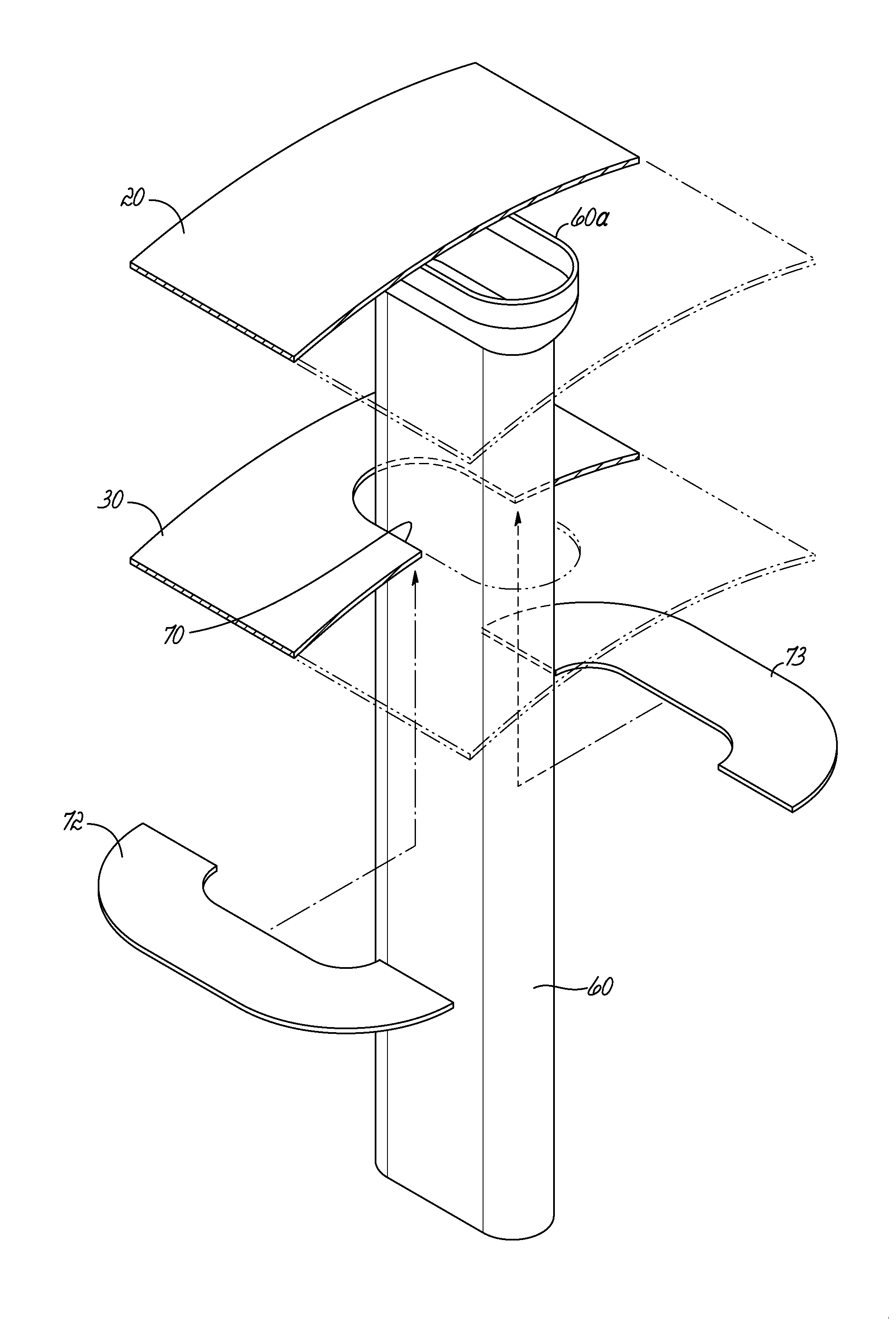
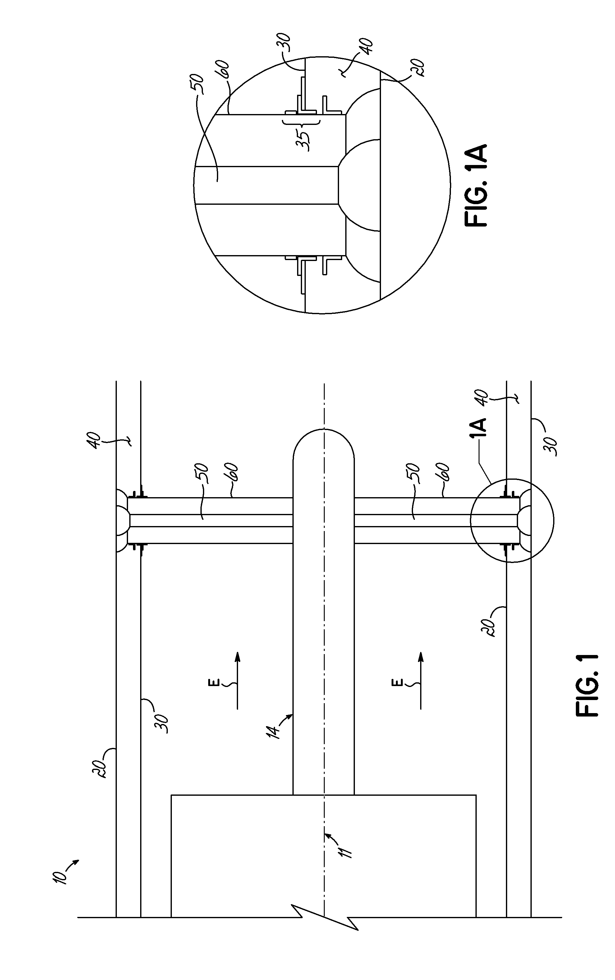
[0028]Turning now to the drawings, FIG. 1 diagrammatically illustrates the invention and its use. A turbine 10 is oriented about a major axis 11. A bearing housing 14 extends rearwardly from the turbine about axis 11 and provides support for a rotary turbine shaft (not shown). An outer exhaust casing 20 in the form of an annulus or cylinder and defining an outer exhaust cylinder extends rearwardly from turbine 10. An inner shield 30 in the form of an annulus or a cylinder and defining an exhaust tunnel also extends rearwardly from turbine 10, radially inward from outer casing 20. The outer casing 20 outwardly surrounds inner shield 30 such that there is an annular dead space 40 between casing 20 and shield 30. Exhaust from turbine T flows in the direction of arrows E.

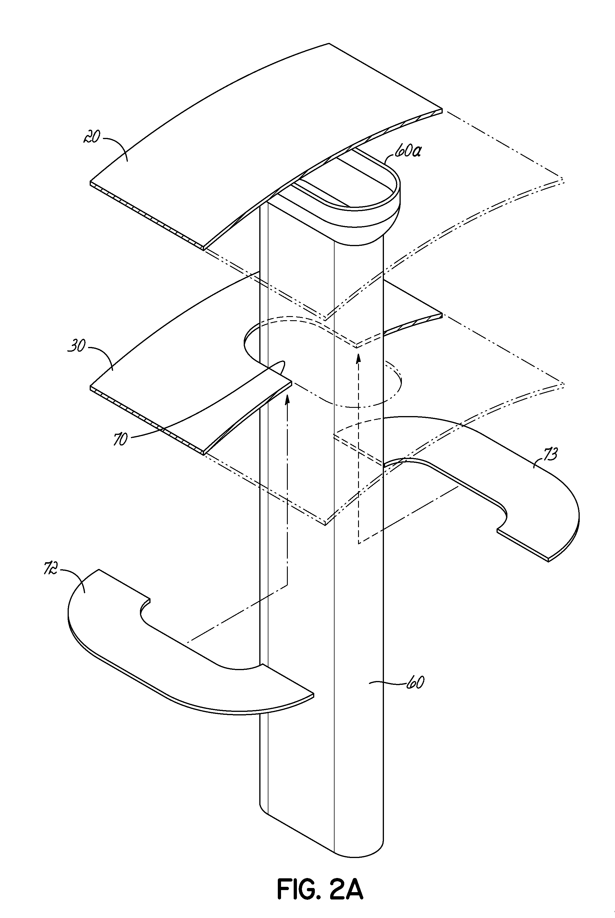
[0029]A series of radially-extending struts 50 extends from outer casing 20 to bearing housing 14, through shield 30 at intersection 35. Struts 50 are encased in strut housing 60 as shown. Struts 50 and housings 60 are ...


PUM


Abstract

Undue flexing and cracking of an internal exhaust shield of a turbine is eliminated by isolating thermally-induced movement in the shield from that of strut apparatus passing therethrough to a surrounding outer exhaust casing. Methods and apparatus are disclosed.

Description

PRIORITY CLAIM[0001]Applicant claims the benefit of the filing date of Feb. 11, 2011 of U.S. provisional patent application Ser. No. 61 / 448,876, the disclosure of which is hereby incorporated herein by reference in its entirety.FIELD OF THE INVENTION[0002]This invention relates to jet turbines, more particularly to land-based turbines used, for example in Combined Cycle Power Generation facilities and even more particularly to the exhaust structures of such turbines and the inherent problems therein of cracking due to differentials in thermal generated expansion and contraction of the respective exhaust components.BACKGROUND OF THE INVENTION[0003]Typically, such turbines include an exhaust structure which comprises an outer exhaust casing in the form of an annulus, and an inner exhaust tunnel defined by an annular exhaust cylinder or shield with an annular dead air space defined between the outer casing and the inner shield. Simply stated, an outer casing or cylinder surrounds an in...

Claims


Application Information

Patent Timeline
IPC IPC(8): F02C7/20
CPCF02C7/20F01D25/30
Inventor SCHUBERT, PAUL C.
Owner EAGLEBURGMANN IND LP
Learn More