Eureka AIR delivers breakthrough ideas for toughest innovation challenges, trusted by R&D personnel around the world.

connector

Active Publication Date: 2012-08-30
JAPAN AVIATION ELECTRONICS IND LTD
View PDF50 Cites 22 Cited by
  • Summary
  • Abstract
  • Description
  • Claims
  • Application Information

AI Technical Summary

Benefits of technology

[0008]It is therefore an object of the present invention to provide a connector having a pressed portion configured to be pressed by a tip of an operation member, wherein the pressed portion is designed to prevent the tip pressing the pressed portion from coming off even if the connector has a relatively small size.

Problems solved by technology

Moreover, the tip of the pin coming off the push lever may damage components which are arranged around a position where the connector is installed.
It is difficult to properly engage the tip of the operation tool with the depression having small size so that the tip may come off the depression.

Method used


Image

  • connector
  • connector
  • connector

Examples


Embodiment Construction

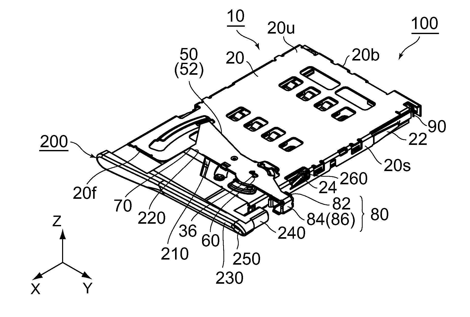
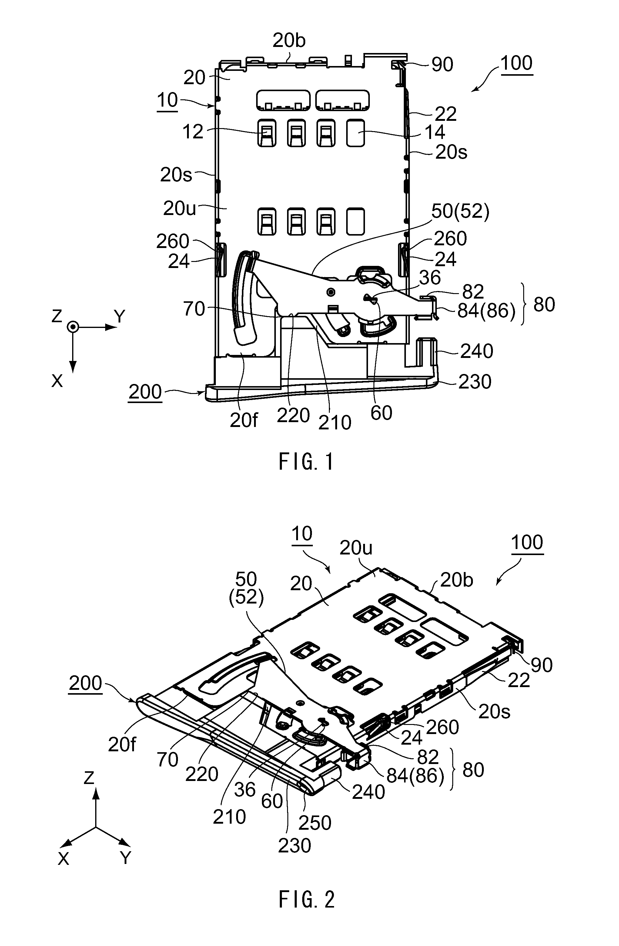
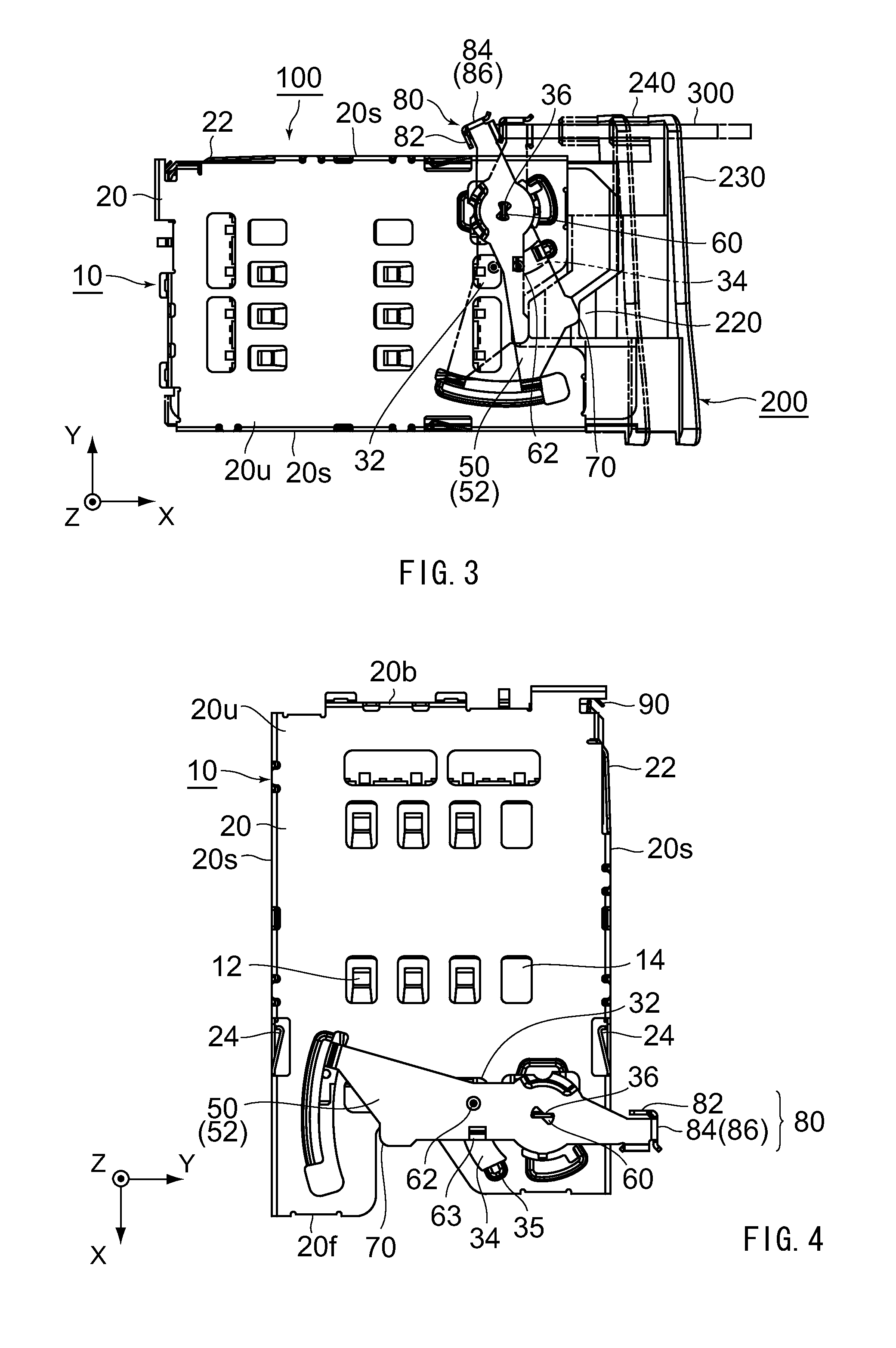
[0024]Referring to FIGS. 1 to 3, a device 100 according to an embodiment of the present invention comprises a tray 200 configured to mount a card (not shown) and a connector 10 configured to accommodate the tray 200 partially. The card (not shown) according to the present embodiment is, for example, a SIM card. The connector 10 is connectable to the card (not shown). More specifically, the connector 10 and the tray 200 are configured so that the tray 200 is insertable into the connector 10 in a state where the card (not shown) is mounted on the tray 200. The card (not shown) mounted on the tray 200 and inserted in the connector 10 is electrically connected to the connector 10.

[0025]As shown in FIGS. 1 to 3, the tray 200 according to the present embodiment is made of a molded resin. The tray 200 is provided with a mount portion 210, a force-applied portion 220, a front wall 230, a rod-like portion 240, a guide channel 250 and two recesses 260. The mount portion 210 is configured to m...


PUM


Abstract

A connector is connectable to a card. The connector comprises an eject member including a pressed portion. The eject member is configured to eject the card along an eject direction when the pressed portion is pressed by an operation member separated from the connector and having a tip. The pressed portion is formed by bending a metal plate so as to have a receiving wall and a side wall. The receiving wall is configured to be brought into abutment with the tip of the operation member so that the pressed portion is pressed by the operation member. The side wall extends in a direction crossing the receiving wall so that the side wall is located lateral to the tip upon the abutment of the tip with the receiving wall.

Description

CROSS REFERENCE TO RELATED APPLICATIONS[0001]Applicants claim priority under 35 U.S.C. §119 of Japanese Patent Application No. JP2011-39047 filed Feb. 24, 2011.BACKGROUND OF THE INVENTION[0002]This invention relates to a connector connectable to a card such as a SIM (Subscriber Identity Module) card.[0003]For example, this type of connectors is disclosed in JP-A 2008-108695 or JP-A H9(1997)-7693, contents of which are incorporated herein by reference.[0004]The connector disclosed in JP-A 2008-108695 is connectable to a memory card such as a MMC (Multi Media Card). The memory card is accommodated in and ejected from the connector in a state where the memory card is mounted on a tray having a hole. In detail, the connector is provided with a lock mechanism to lock the tray therein and a push lever configured to be operated by a pin (operation member) having a tip. The push lever is pressed by the tip of the pin inserted through the hole of the tray so that the tray is unlocked. The tr...

Claims


Application Information

Patent Timeline
IPC IPC(8): H01R13/62
CPCG06K13/0806
Inventor YOKOYAMA, YOHEIKATAYANAGI, MASAYUKI
Owner JAPAN AVIATION ELECTRONICS IND LTD
Why Eureka
Eureka Blog
Learn More