Cutting assembly

a technology of cutting assembly and cutting insert, which is applied in the direction of shaping cutters, tool holders, manufacturing tools, etc., can solve the problems of increasing the difficulty of coolant delivery to the cutting insert-workpiece interface, and achieve the effect of improving the difficulty of connecting coolant to the cutting insert and the workpiece interfa

Active Publication Date: 2012-09-13
KENNAMETAL INC
View PDF25 Cites 57 Cited by
  • Summary
  • Abstract
  • Description
  • Claims
  • Application Information

AI Technical Summary

Problems solved by technology

During the cutting operation, as the depth of the groove increases, the difficulty connected with coolant delivery to the cutting insert-workpiece interface increases.

Method used


Image

  • Cutting assembly
  • Cutting assembly
  • Cutting assembly

Examples


Embodiment Construction

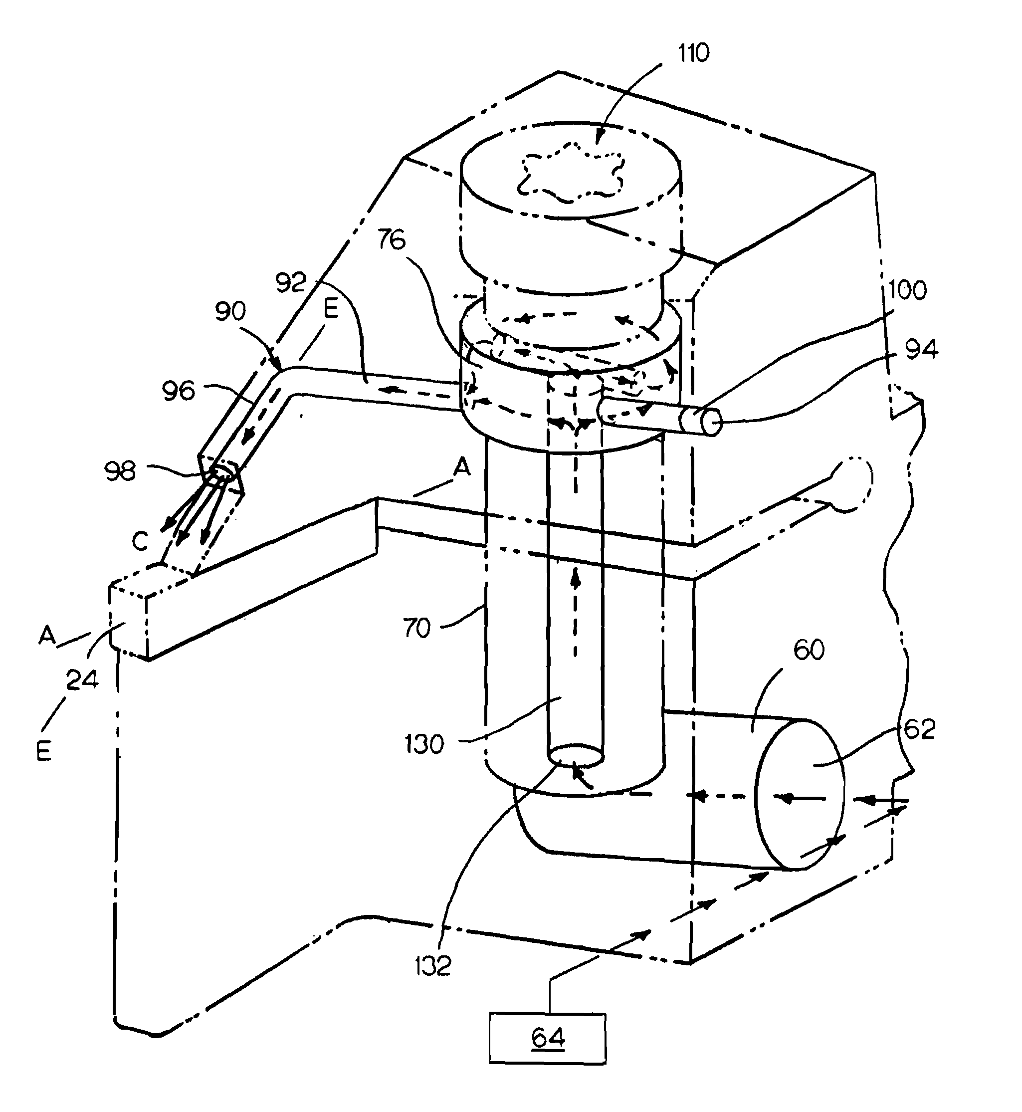
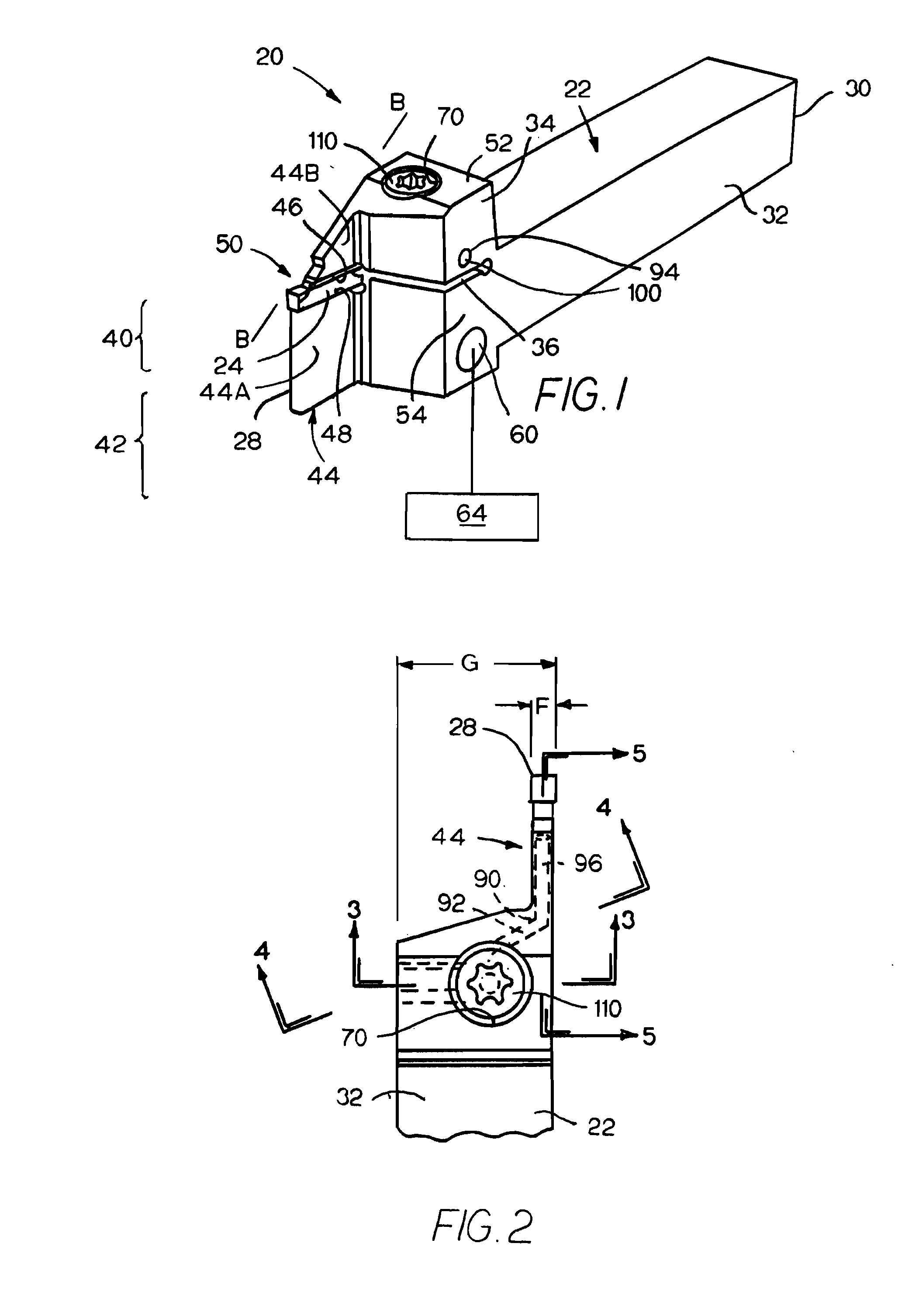
[0017]Referring to the drawings and in particular to FIG. 1, there is illustrated a cutting assembly generally designated as 20. The specific kind of cutting assembly 20 illustrated is a grooving assembly. The illustration of a grooving assembly is not intended to restrict the scope of the invention. Further, the mention of the cutting assembly and cutting insert as a grooving assembly and grooving insert is not intended to restrict the scope of the invention. The kinds of cutting assemblies to which the invention relates includes, without limitation, a turning assembly, a cut-off tool assembly, and a face grooving assembly. The true scope and spirit of the invention is indicated by the claims hereof.

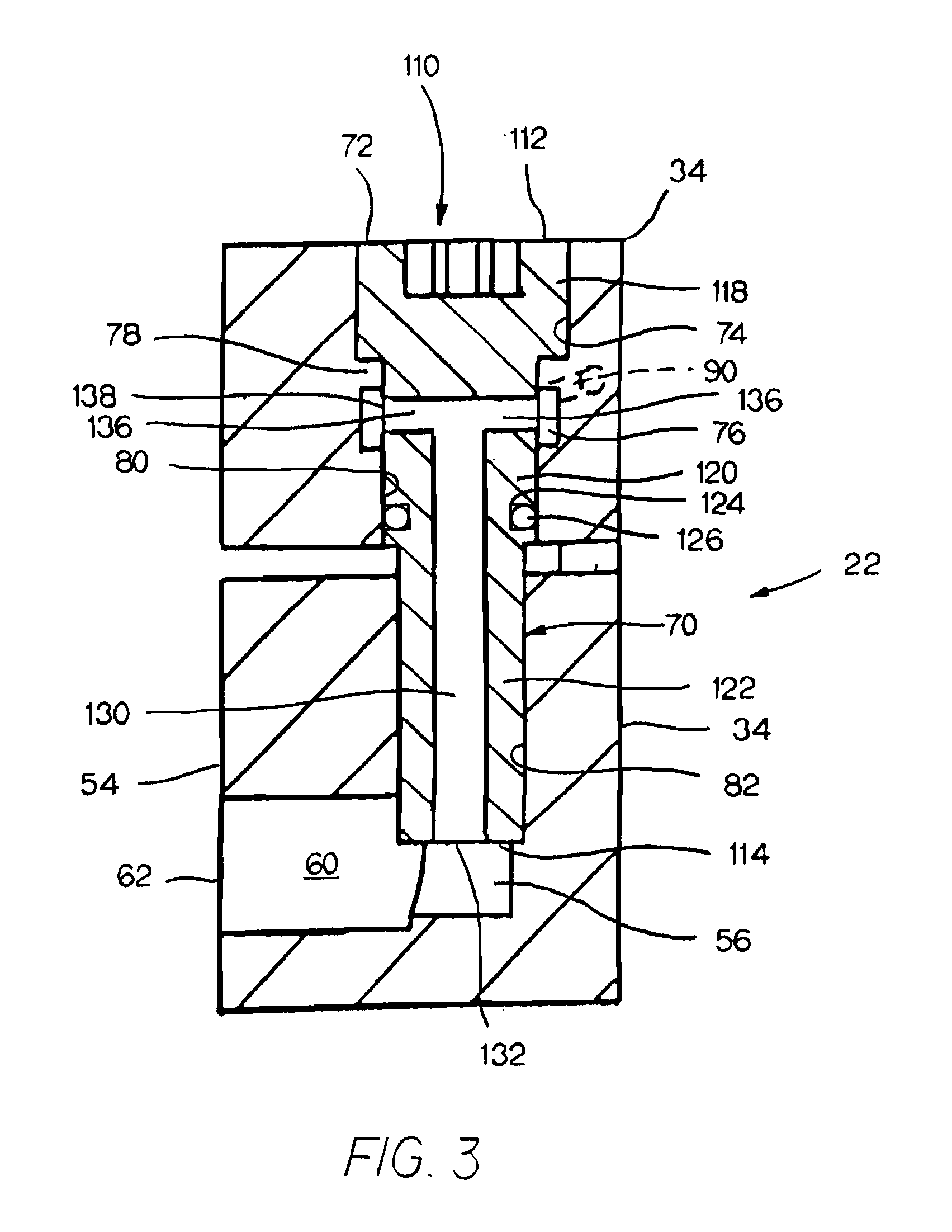
[0018]Cutting (or grooving) assembly 20 comprises a toolholder 22 and a cutting insert (or grooving insert) 24. As shown in FIG. 6, the cutting insert 24 has a central longitudinal cutting insert axis A-A. As will be discussed hereinafter, the cutting insert is secured in the toolholder...


PUM

PropertyMeasurementUnit
diameteraaaaaaaaaa
depthaaaaaaaaaa
transverse dimensionaaaaaaaaaa

Abstract

A toolholder has a head region, which contains a slot separating the head region into a lower section and an upper section, with a lower seat and an upper section to retain a cutting insert. The head region contains a coolant entrance passage, which receives coolant from a coolant source, and a coolant delivery passage, which discharges coolant toward a cutting insert. The head region further contains a fastener bore, which receives a fastener. The fastener has an axial fastener bore which provides fluid communication between the coolant entrance passage and a coolant reservoir between the fastener and the fastener bore. The coolant delivery passage communicates with the coolant reservoir to receive coolant, which passed from the coolant entrance passage and through the axial fastener bore into the coolant reservoir.

Description

BACKGROUND OF THE INVENTION[0001]The invention pertains to a cutting assembly for removing material from a workpiece. More specifically, the invention pertains to such a cutting assembly that includes a toolholder, which carries a cutting insert, wherein the toolholder provides the capability to supply coolant to the cutting insert.[0002]In a cutting operation, such as, for example, a grooving operation, a grooving or cutting insert engages a workpiece so as to remove material from the workpiece. In some cutting assemblies, an upper seat and a lower seat retain the cutting insert. Exemplary cutting assemblies wherein an upper seat and a lower seat retain a cutting insert are shown in U.S. Pat. No. 6,261,032 to Duwe et al. and PCT Patent Application Publication WO 2009 / 141815 A1 to Iscar, Ltd.[0003]Material removal operations can generate heat at the interface between the cutting insert and the workpiece. Typically, it is advantageous to provide coolant to the vicinity of the interfa...

Claims


Application Information

Patent Timeline
Patent Type & Authority Applications(United States)
IPC IPC(8): B23B27/10
CPCB23B27/10B23B29/043Y10T407/227Y10T407/25Y10T407/14Y10T407/2286
Inventor HENRY, NICHOLAS J.CONWAY, CHARLES L.
Owner KENNAMETAL INC
Why Eureka
Try Eureka