Plastic bag making apparatus

a bag making and plastic bag technology, applied in box making operations, paper/cardboard containers, paper/cardboard articles, etc., can solve the problem that the structure of the panel material guide means is complicated

Active Publication Date: 2012-09-13
TOTANI CORP (JP)
View PDF2 Cites 23 Cited by
  • Summary
  • Abstract
  • Description
  • Claims
  • Application Information

AI Technical Summary

Benefits of technology

[0011]In a preferred embodiment, the apparatus further includes a cutter by which the web of bottom gusset material, the webs of panel material and the sheet of side gusset material are cut widthwise of the webs of panel material whenever the webs of panel material are fed intermittently and with the open surfaces kept being formed.

Problems solved by technology

Accordingly, the panel material guide means must be complicated in structure.

Method used


Image

  • Plastic bag making apparatus
  • Plastic bag making apparatus
  • Plastic bag making apparatus

Examples


Embodiment Construction

[0021]Embodiments of the invention are as follows.

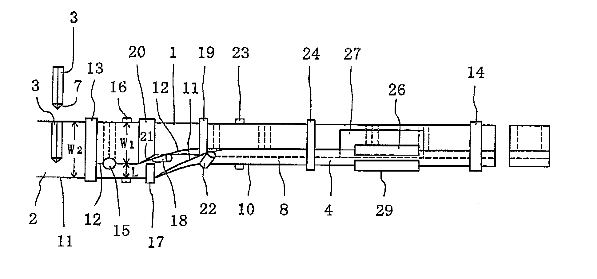
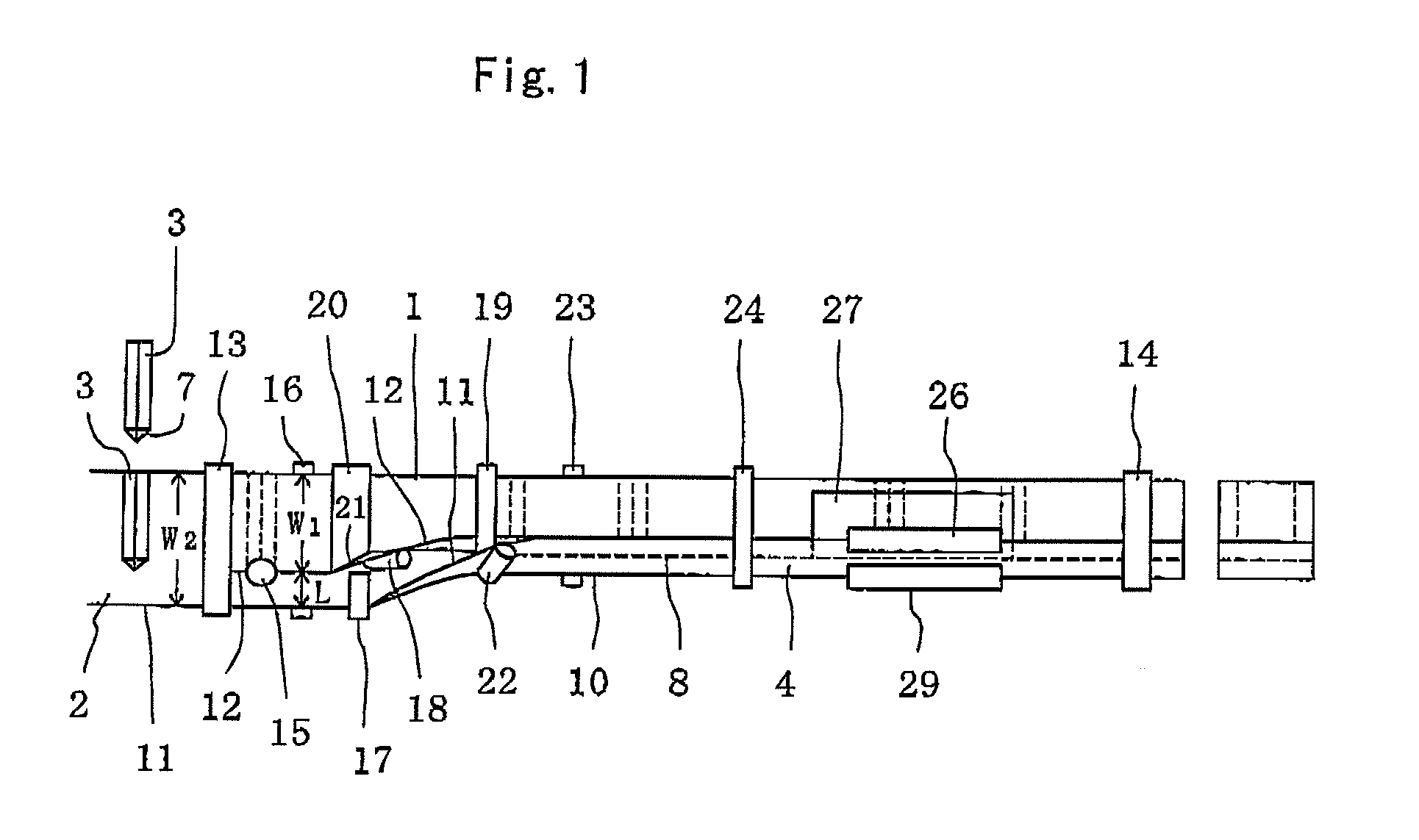
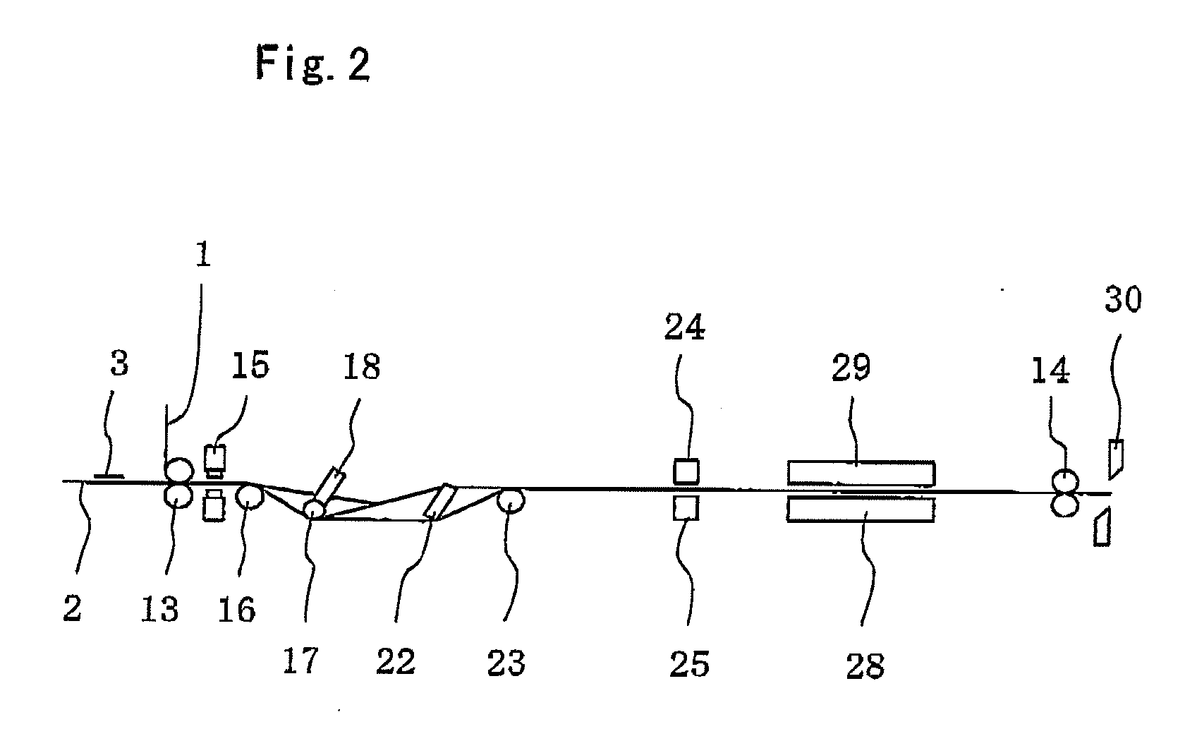
[0022]Turning now to the drawings, FIG. 1 illustrates an apparatus for successively making plastic bags, according to the invention. Each of the plastic bags includes panel portions 1 and 2, side gusset portions 3 and a bottom gusset portion 4, as shown in FIG. 3 and as in the case of the plastic bag of U.S. Pat. No. 7,331,917. The panel portions 1 and 2 are superposed on each other to have opposite side edges 5 along which the side gusset portions 3 extend, as shown in FIG. 4. The side gusset portions 3 are folded into halves, superposed into two layers and interposed between the panel portions 1 and 2. The panel portions 1 and 2 and the side gusset portions 3 are heat sealed with each other along the side edges 5 of panel portions 1 and 2 so that heat sealed lines 6 can be formed along the side edges 5. In addition, each of the side gusset portions 3 has opposite end portions at one of which an auxiliary gusset portion 7 is formed....


PUM


Abstract

A sheet of side gusset material 3 is folded into halves, superposed into two layers and interposed between webs of panel material 1 and 2. One of the webs of panel material 1 is folded along a longitudinal folded line 8 to make the webs of panel material 1 and 2 open and make an open surface formed on the webs of panel material 1 and 2. One of the layers of side gusset material 3 is folded along the longitudinal folded line 8 to make the layers of side gusset material 3 open along with an auxiliary gusset portion 7 and make an open surface formed on the layers of auxiliary gusset portion 7. A web of bottom gusset material 4 is superposed on the open surfaces of panel material 1 and 2 and auxiliary gusset portion 7. The web of bottom gusset material 4 and the auxiliary gusset portion 7 are heat sealed with each other while the webs of panel material 1 and 2 and the sheet of side gusset material 3 are heat sealed with each other widthwise of the webs of panel material 1 and 2 with the open surfaces kept being formed. The web of bottom gusset material 4 and at least one of the webs of panel material 1 are heat sealed with each other longitudinally of the webs of panel material 1 and 2 with the open surfaces kept being formed.

Description

TECHNICAL FIELD[0001]The invention relates to an apparatus for successively making plastic bags.BACKGROUND[0002]An apparatus has heretofore been developed and proposed to successively make plastic bags each of which includes panel portions, side gusset portions and a bottom gusset portion, as disclosed in U.S. Pat. No. 7,331.917. Each of the side gusset portions has opposite end portions at one of which an auxiliary gusset portion is formed. The bottom gusset portion is combined with the auxiliary gusset portion. The plastic bag is called a rectangular bottom bag.[0003]In the apparatus, webs of panel material are superposed on each other and fed longitudinally thereof and intermittently. The panel portions are formed by the webs of panel material. A sheet of side gusset material is folded into halves, superposed into two layers and then supplied to and interposed between the webs of panel material to extend widthwise thereof whenever the webs of panel material are fed intermittently...

Claims


Application Information

Patent Timeline
Patent Type & Authority Applications(United States)
IPC IPC(8): B31B1/64B31B50/64
CPCB31B1/64B31B2219/146B31B2219/2681B31B2219/6038B31B2237/60B31B2219/6061B31B2237/20B31B2237/406B31B2237/50B31B2219/6053B31B50/00B31B70/18B31B70/262B31B70/642B31B70/644B31B70/645B31B2155/00B31B2155/0014B31B2155/002B31B2155/003B31B2160/20
Inventor SENBO, TOMOHIKO
Owner TOTANI CORP (JP)
Why Eureka
Try Eureka