Steam Sauna for the Lower Body

a technology for the lower body and steam sauna, which is applied in the field of steam sauna for the lower body, can solve the problems of not having a combination of foot massagers and raised rotating nodes in prior art, and no one utilizes steam to hydrate the entire lower body

Inactive Publication Date: 2012-10-04
HUYNH KEVIN
View PDF9 Cites 24 Cited by
  • Summary
  • Abstract
  • Description
  • Claims
  • Application Information

AI Technical Summary

Problems solved by technology

None of the prior art utilizes steam to hydrate the entire lower body portions.
The prior art also does not contain cut-outs in the walls of hydrators to provide support underneath the user's knees.
Further, the prior art does not contain a foot massager with raised rotating nodes combined with a steam outlet to massage or hydrate the feet.
None of the prior art can be combined in this way to suggest these necessary modifications to increase hydration and circulation to the user's entire lower body portions.
There is no teaching, suggestion, or motivation in the prior art that would have enabled a person of ordinary skill in the art to modify any prior art foot massager or bath apparatus to allow steam and raised nodes to hydrate and massage a user's entire lower body portions and hands.
U.S. Pat. No. 2,265,484 discloses the use of boiler or electric heater generated steam to aid in relieving medical ailments, however, it does not disclose any form of massage and is limited to use by small parts of the body such as the hands and neck.
U.S. Patent Publication 2006 / 0195979 discloses the use of hot and cold water and raised nodes to massage the user's feet, however, the steam generated by the device is an unintended side effect of using hot water.
U.S. Pat. No. 6,393,633 discloses the use of hot water and raised nodes to massage the user's feet, however, it does not disclose the use of steam to hydrate the feet and it does not treat the user's entire lower body portions.
The prior art to date does not disclose a steam chamber with cut-outs to provide support underneath the user's knees, a steam generator, a steam distribution apparatus, and a foot massager with a steam outlet to hydrate and massage the user's entire lower body portions and hands.
None of the prior art can be combined in this way to suggest these necessary modifications.
There is no teaching, suggestion, or motivation that would have enabled a person of ordinary skill in the art to modify any prior art foot massager or bath apparatus to allow steam and raised nodes to hydrate and massage a user's entire lower body portions and hands.

Method used


Image

  • Steam Sauna for the Lower Body
  • Steam Sauna for the Lower Body
  • Steam Sauna for the Lower Body

Examples


Embodiment Construction

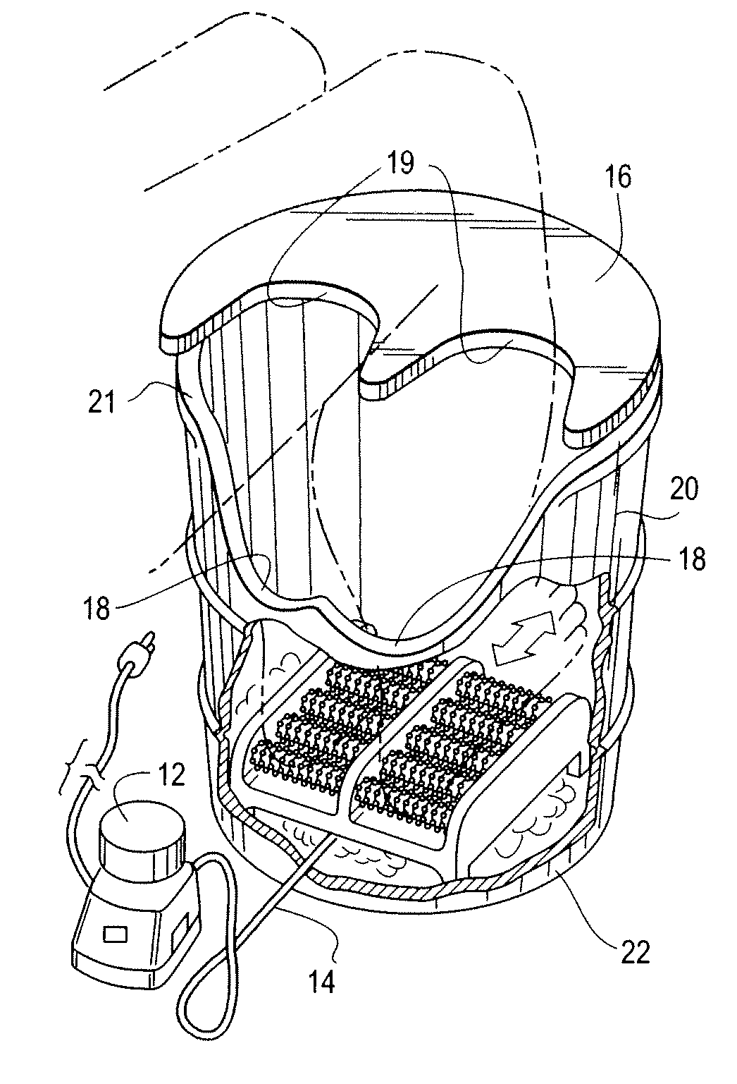
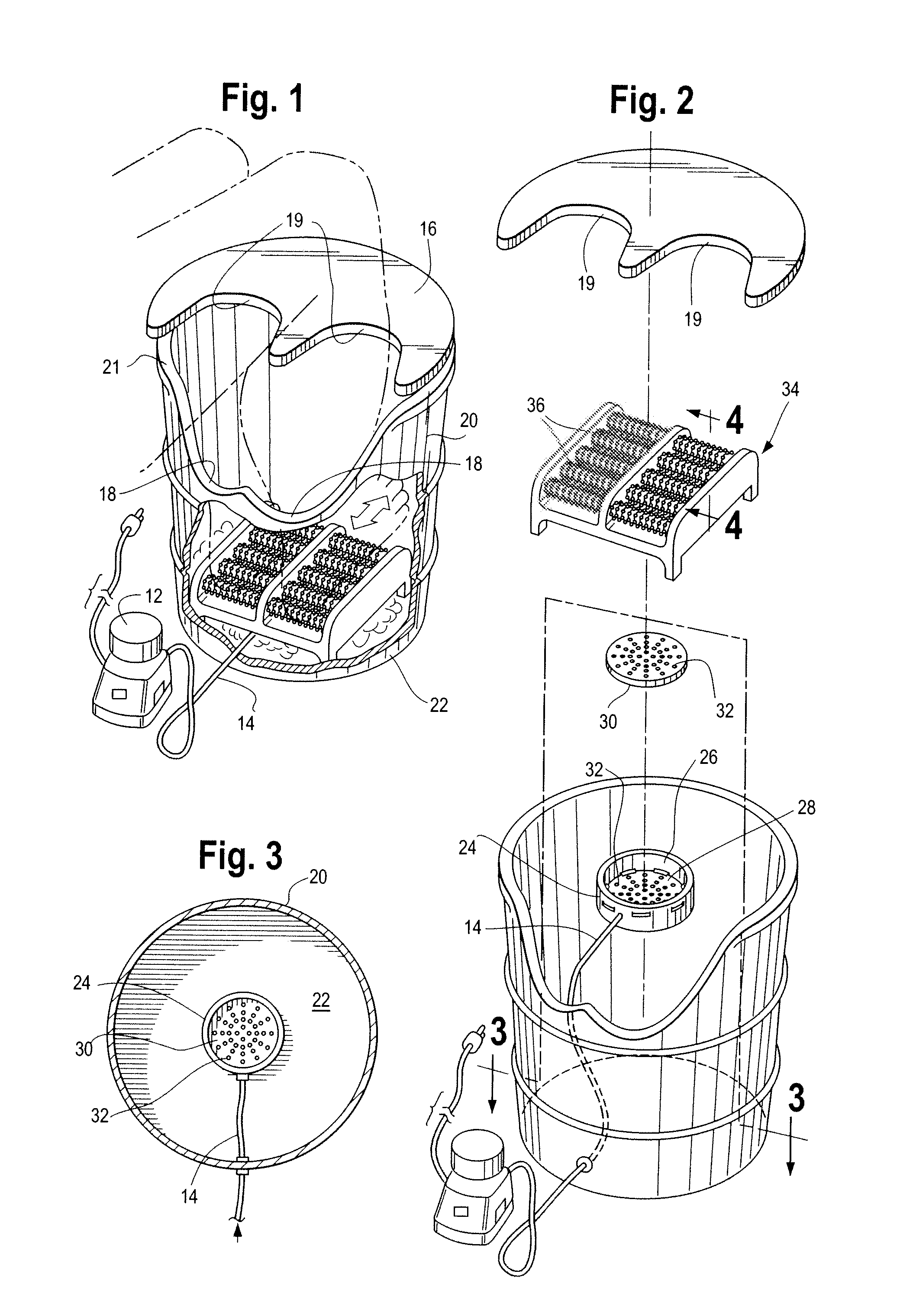
[0023]Referring to FIGS. 1 and 2, the steam sauna of the invention comprises a container having a chamber 10. Chamber 10 has a wall structure 20 open at the top end 21 and a bottom surface 22. The top end 21 of wall structure 20 supports a removable lid 16. The wall structure 20 includes at least one cut-out portion of two adjacent curvilinear forms 18 on an edge of wall structure 20, which curvilinear forms 18 are adapted to receive and support the lower body parts of the user. The wall structure 20 also receives a hose or tube 14, which is in communication on one end to a steam generator 12 located outside of chamber 10, and with chamber 10 at the opposite end. As seen in FIG. 2, removable lid 16 also includes two adjacent curvilinear forms 19, for purposes to be explained.

[0024]Referring to FIGS. 2 and 3, the end of hose 14 passing through the wall structure 20 of chamber 10 is in communication with the steam distribution apparatus 24. The steam distribution apparatus 24 is locat...


PUM


Abstract

An apparatus for hydrating the lower body portions and / or hands of a user. The apparatus includes a chamber for receiving and containing steam and the lower body portions and / or hands of the user. The chamber includes a bottom surface and a wall structure extending upwardly from the bottom surface. Steam from the steam generator is transported via a hose in communication with the steam generator and the chamber. Inside the chamber, the hose is in communication with a steam distribution apparatus. Steam passing through the steam distribution apparatus fills the chamber.

Description

BACKGROUND OF THE INVENTION[0001]1. Field of the Invention[0002]The present invention relates to an apparatus for hydrating and massaging the lower body portions and hands of a user.[0003]2. Description of the Prior Art[0004]Foot hydrators and massagers are well known. The foot hydrators and massagers of the prior art typically utilize hot water, water agitation, and a plurality of raised nodes to massage the feet. None of the prior art utilizes steam to hydrate the entire lower body portions. The prior art also does not contain cut-outs in the walls of hydrators to provide support underneath the user's knees. Further, the prior art does not contain a foot massager with raised rotating nodes combined with a steam outlet to massage or hydrate the feet. None of the prior art can be combined in this way to suggest these necessary modifications to increase hydration and circulation to the user's entire lower body portions. There is no teaching, suggestion, or motivation in the prior art...

Claims


Application Information

Patent Timeline
Patent Type & Authority Applications(United States)
IPC IPC(8): A61H33/06
CPCA61H33/065A61H35/006A61H2015/0014A61H2205/102A61H2201/1695A61H2205/065A61H2033/068
Inventor HUYNH, KEVIN
Owner HUYNH KEVIN
Why Eureka
Try Eureka