

Liquid crystal display device
a liquid crystal display and display device technology, applied in optics, instruments, electrical equipment, etc., can solve the problems of affecting the interface between ordinary light and extraordinary light, affecting the uniformity of the electric field applied to the liquid crystal in longitudinal and transverse directions, and affecting the effect of the polarized sunglasses
- Summary
- Abstract
- Description
- Claims
- Application Information
AI Technical Summary
Benefits of technology
Problems solved by technology
Method used
Image

Examples
example 1
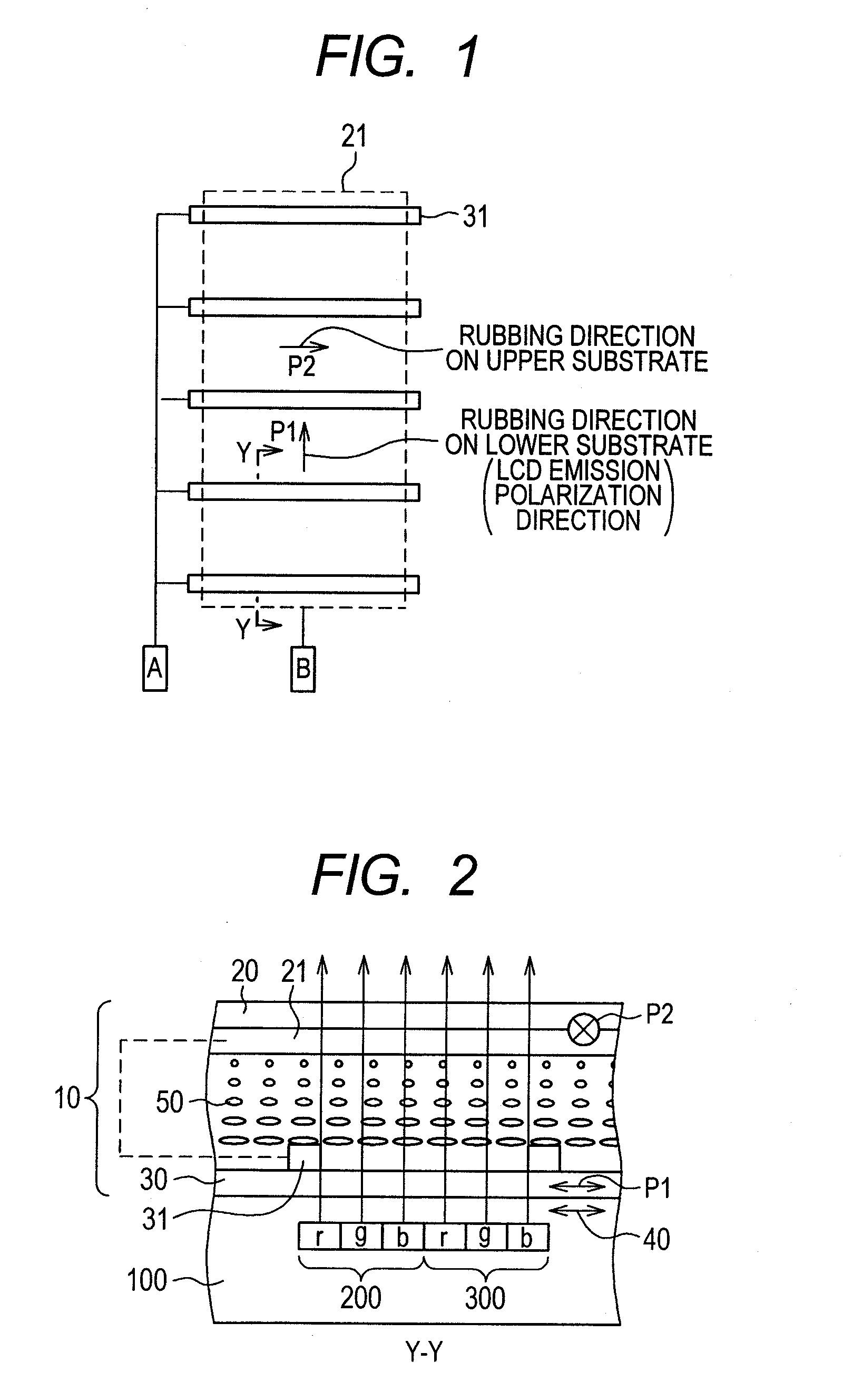
[0061]FIG. 1 is a plan view illustrating the electrode structure of the liquid crystal lens 10 according to Example 1, and the rubbing directions on the upper substrate 20 and the lower substrate 30. The electrode structure shown in FIG. 1 is the same as the electrode structure shown in FIG. 10, and the explanation thereof, thus will be omitted. The structure shown in FIG. 1 is different from the one shown in FIG. 10 in the rubbing direction on the upper substrate 20. The rubbing direction on the lower substrate 30 is vertical with respect to the extending direction of the lower substrate electrode pattern 31 in the same manner as the structure shown in FIG. 10. The rubbing direction on the upper substrate 20 is the same as the extending direction of the lower substrate electrode pattern 31. Therefore, the initial alignment of the liquid crystal molecules interposed between the upper substrate 20 and the lower substrate 30 is twisted.
[0062]FIG. 2 is a sectional view of the liquid cr...
example 2
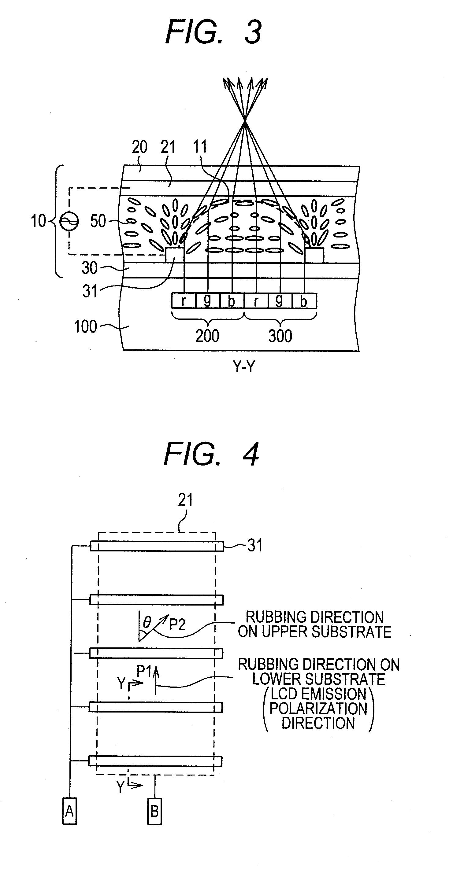
[0065]FIG. 4 is a plan view of Example 2 according to the present invention, which is the same as Example 1 shown in FIG. 1 except the rubbing direction P2 on the upper substrate 20. Referring to FIG. 4, the rubbing direction P2 on the upper substrate 20 is tilted at a predetermined angle θ with respect to the rubbing direction P1 on the lower substrate 30.
[0066]The aforementioned structure allows the viewer to visually recognize the 3D image of the liquid crystal lens 10 using the polarized sunglasses 400. If the predetermined angle θ is equal to 90° exactly, the viewer is capable of visually recognizing the brightest 3D image. However, the viewer is also capable of visually recognizing the 3D image with the predetermined brightness even when the angle θ is not 90°. That is, application of the polarized sunglasses 400 may avoid the case where the image is completely invisible like the related art.
[0067]In the structure of this example having the angle θ set to 45°, the 2D image on ...
example 3
[0068]On demand from recent application of the liquid crystal display device, the function capable of selectively displaying in the portrait mode (vertical display) and the landscape mode (horizontal display) has been added, like the mobile phone. To cope with the application, the 3D panel is required to have the function for selecting the display between the vertical and horizontal modes. The generally employed liquid crystal lens structure capable of selectively displaying the 3D images and its problem have been described referring to FIGS. 22 and 23 to 26 as sectional views thereof.
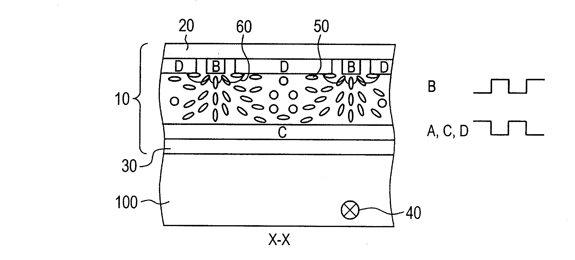
[0069]The most notable problem of the related art as shown in FIG. 26 is that the transverse electric field is generated between the electrodes B and D on the upper substrate, and the liquid crystal is aligned again along the electric field. The transverse electric field not only disrupts the configuration of the liquid crystal lens 10 but also causes the lens effect to disappear over a long time as th...
PUM
| Property | Measurement | Unit |
|---|---|---|
| angle | aaaaa | aaaaa |
| angle | aaaaa | aaaaa |
| angle | aaaaa | aaaaa |
Abstract
Description
Claims
Application Information