System and method for creating a decision support material indicating damage to an anatomical joint

a decision support and anatomical joint technology, applied in the field of systems and methods for creating decision support materials, can solve the problems of not being able to judge the extent of the damage to the joint using just bml detection, and not being able to draw definite conclusions regarding the cartilage status or the functioning of the joint, etc., to achieve the effect of simplifying the marking process

Active Publication Date: 2017-07-04
EPISURF IP MANAGEMENT
View PDF10 Cites 5 Cited by
  • Summary
  • Abstract
  • Description
  • Claims
  • Application Information

AI Technical Summary

Benefits of technology

[0014]The above described problems are also addressed by the claimed method for creating a decision support material indicating damage to at least a part of an anatomical joint of a patient, wherein the created decision support material comprises one or more damage images. The method comprises the steps of: i) receiving a series of radiology images of the at least part of the anatomical joint; ii) obtaining a three-dimensional image representation of the at least part of the anatomical joint which is based on said series of radiology images by generating said three-dimensional image representation in an image segmentation process based on said radiology images, or receiving said three-dimensional image representation from the storage media; iii) identifying tissue parts of the anatomical joint, including at least cartilage, tendons and / or ligaments, in at least one of the series of radiology images using image analysis; iv) determining damage to the anatomical joint by analyzing said at least one of the series of radiology images and / or the three-dimensional image representation of the at least part of the anatomical joint using the identified tissue parts and a selection of: detecting an irregular shape of a contour of at least one tissue part of the anatomical joint; and / or detecting that the intensity in an area within or adjacent to bone and / or cartilage parts of the anatomical joint is higher or lower than a predetermined value; and / or comparing at least one identified tissue part with a template representing a predefined damage pattern for an anatomical joint; v) marking damage to the anatomical joint in the obtained three-dimensional image representation of the at least part of the anatomical joint; and v) generating a decision support material, where the determined damage to the anatomical joint is marked in at least one of the one or more damage images of the decision support material, and at least one of the damage images is generated based on the obtained three-dimensional image representation of the at least part of the anatomical joint. The claimed method creates a decision support material which clearly visualizes the extent of damage to the joint or a part of the joint.
[0019]The above described problems are also addressed by a decision support material indicating damage to at least a part of an anatomical joint of a patient, wherein the decision support material comprises one or more damage images generated by the method steps of any one of the above described methods.
[0020]The above described problems are also addressed by a non-transitory machine-readable medium on which is stored machine-readable code which, when executed by a processor, controls the processor to perform any one of the above described methods.

Problems solved by technology

This does not provide conclusive information regarding anything except the cancellous bone—it is not possible to draw definite conclusions regarding the cartilage status or the functioning of the joint.
Further, it is not possible to judge the extent of the damage to a joint using just BML detection.
If the image analysis identifies both bone parts and cartilage parts of the anatomical joint, damage may be determined to both the bone parts and the cartilage parts.

Method used


Image

  • System and method for creating a decision support material indicating damage to an anatomical joint
  • System and method for creating a decision support material indicating damage to an anatomical joint
  • System and method for creating a decision support material indicating damage to an anatomical joint

Examples


use case embodiment

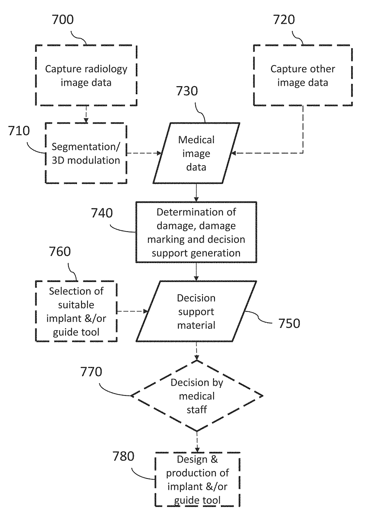
[0125]To set the presently disclosed methods and systems in a larger context, the damage marking and the generation of one or more damage images, and / or damage report, according to any of the disclosed embodiments, may in use case embodiments be preceded by capturing and / or obtaining medical image data representing an anatomical joint or part of it, and may further be followed by actions to be taken in view of repairing any determined damage.

[0126]FIG. 7 is a flow diagram exemplifying one such larger context, including obtaining medical image data from an image source, determining damage to a depicted anatomical joint and generating a damage image or damage report in accordance with one or more embodiments described herein. FIG. 7 further includes steps of designing and producing an implant and / or guide tool suitable for repairing a determined damage in an anatomical joint. In FIG. 7, everything except the determination of damage, damage marking and decision support material generat...


PUM


Abstract

A system for creating decision support material indicating damage to an anatomical joint of a patient. The system is configured to: i) receive a series of radiology images of at least a part of the anatomical joint; ii) obtain a three-dimensional image representation of the at least part of the anatomical joint; iii) identify tissue parts of the anatomical joint using image analysis; iv) determine damage to the anatomical joint by analyzing said image representation; v) mark damage to the anatomical joint in the obtained three-dimensional image representation; and vi) generate decision support material. The analysis comprises: detecting an irregular shape of a contour of a tissue part; and / or detecting that the intensity in an area within or adjacent to bone and / or cartilage parts differs from a predetermined value; and / or comparing at least one identified tissue part with a template representing a predefined damage pattern for an anatomical joint.

Description

CROSS-REFERENCE TO RELATED APPLICATION[0001]This application claims benefit of EP Application No. 15201361.1, filed Dec. 18, 2015, the content of which is incorporated by reference herein in its entirety.TECHNICAL FIELD[0002]The present disclosure relates generally to systems and methods for creating a decision support material indicating damage to at least a part of an anatomical joint of a patient.BACKGROUND[0003]In order to determine damage to an anatomical joint, it is common in medical practice today to use imaging techniques to depict the anatomical joint of interest and further to have a medical expert analyze the captured image data to determine whether there is damage. The medical expert then makes annotations about the conclusions drawn from the analysis of image data. The annotations are made available to a surgeon or orthopedic staff member who uses the annotations and the captured image data as a decision support for diagnosis and decision of suitable treatment of the p...

Claims


Application Information

Patent Timeline
Patent Type & Authority Patents(United States)
IPC IPC(8): G06K9/00G06T17/00G06T7/13G06T7/00A61B6/00G06T15/00A61B34/10G06K9/62
CPCG06T7/0012A61B6/505A61B6/5217A61B34/10G06K9/6201G06K9/6267G06T7/13G06T15/00G06T17/00A61B2034/107A61B2034/108G06T2207/30008G06T2207/30204A61B6/466A61B6/5211A61F2/30756A61B2034/102A61F2/30942G06T2207/10116A61B2034/105G16H30/40G16H50/70G16H50/20G16H30/20G06T7/55G06T7/0014G06T7/11G06T2210/41G06F18/22G06F18/24
Inventor LILLIESTRALE, RICHARDKARLSSON, ANDERSSPANGBERG, JEANETTEBAKE, NINA
Owner EPISURF IP MANAGEMENT
Why Eureka
Try Eureka