X-ray device

a technology of x-ray detector and diaphragm, which is applied in the direction of radiation diagnostic diaphragm, application, and use of diaphragm/collimeter, etc., can solve the problem that the x-ray detector cannot be electrically controlled asymmetrically, and achieve the effects of facilitating diagnosis c, facilitating visualization on the monitor, and facilitating selection of the desired area

Inactive Publication Date: 2007-05-01
SIEMENS HEALTHCARE GMBH
View PDF9 Cites 4 Cited by
  • Summary
  • Abstract
  • Description
  • Claims
  • Application Information

AI Technical Summary

Benefits of technology

[0004]An object of the invention is to create an X-ray device with a detector which can be positioned at the side of a patient at a different distance across its detector surface, which expands the application possibilities of a large detector in the sense of an improved patient access. A problem of this type arises in particular with an X-ray device with a C-arm carrier system.
[0006]The X-ray device according to the invention allows the diaphragm to be adjusted and the detector to be controlled in such a way that only a partial area of the detector close to the patient is exposed to X-rays, and / or that only the partial area close to the patient is read out. One advantage resulting from the partial area reading-out in that the read-out process can be carried out more quickly so that the calculation time can be saved and examinations can be carried out with a higher image frequency. One special advantage results from the patient proximity to the partial area provided according to the invention, in that the same detector can now be used for examinations, whereby said detector has hitherto been too large for use in a known X-ray device.
[0011]In addition to its asymmetrically controllable detector, the outstanding feature of the X-ray device according to the invention is the asymmetrically moveable diaphragm. The diaphragm is asymmetrically moveable in comparison with other known X-ray devices, thereby allowing the diaphragm and the detector to be controlled in a coordinated manner. If for instance, the detector is controlled such that a partial area is read-out, the diaphragm can be moved so that the faded-in examination area corresponds to this subarea of the detector surface. This design of the diaphragm primarily serves to protect the patient from any unnecessary exposure to radiation.
[0014]The full functionality of the digital zoom is provided for the asymmetrical image area which can be selected by a doctor, such that the diagnosis c an be facilitated based on the monitor image displayed in real-time.
[0015]It is also possible to adjust the diaphragm, in particular a depth diaphragm, symmetrically in respect of the X-ray tube and only to move the detector. In this case, an asymmetrical detector area can be selected, whereby the isocenter of the X-ray tube can simultaneously be maintained. The selection of the desired area is particularly simple and the visualization on the monitor is particularly clear.

Problems solved by technology

A problem of this type arises in particular with an X-ray device with a C-arm carrier system.
EP 0 908 743 A2 discloses an asymmetric ally designed X-ray detector, however this X-ray detector can not be electrically controlled asymmetrically, but it is asymmetrical in terms of its structural edge-side design which is adapted to the anatomy of a body region to be examined.

Method used


Image

  • X-ray device
  • X-ray device
  • X-ray device

Examples


Embodiment Construction

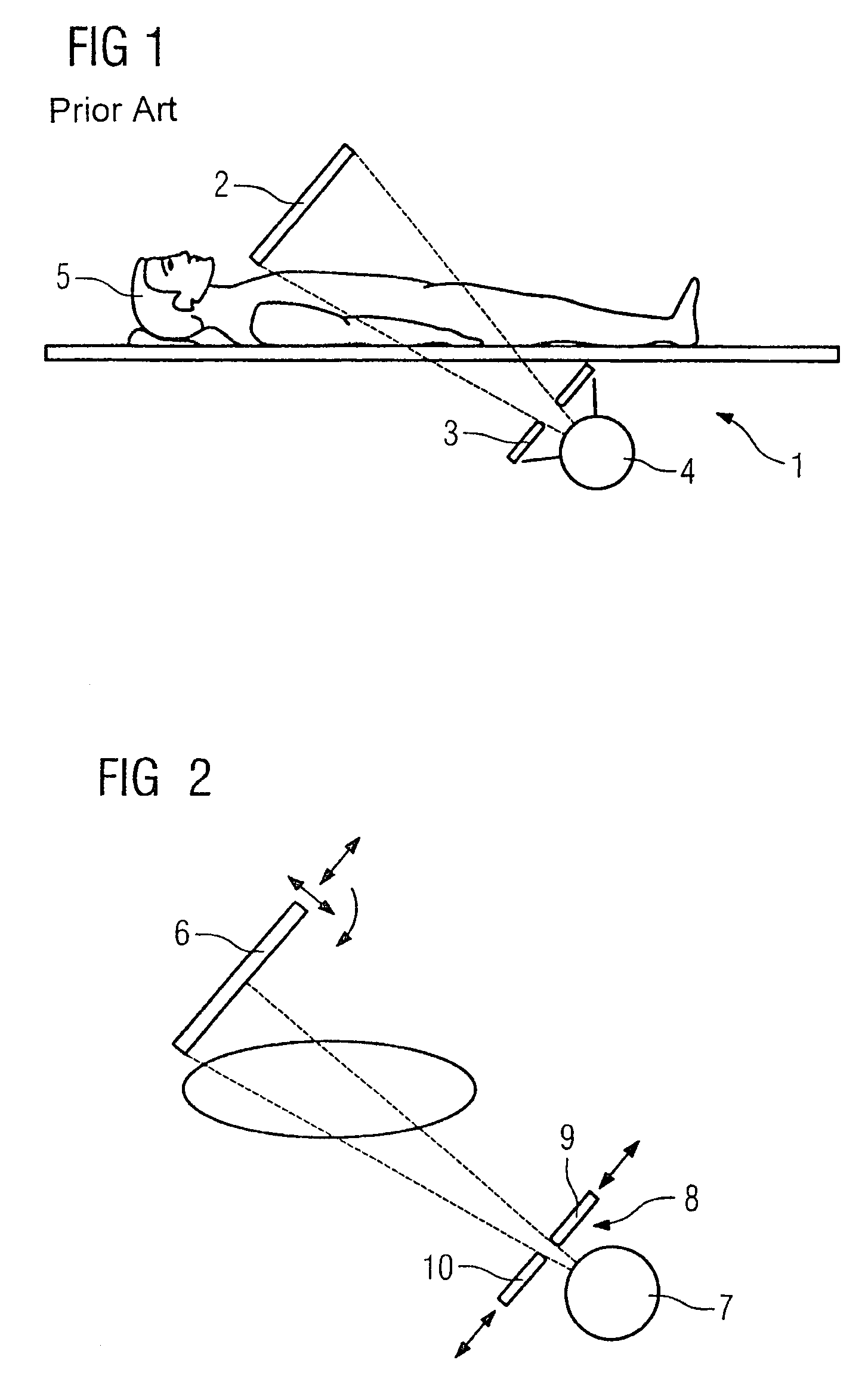
[0022]FIG. 1 shows a conventional X-ray device 1 with a detector 2 and an adjustable diaphragm 3. The diaphragm 3 is located between an X-ray tube 4 and a patient 5 and allows the examination area to be precisely faded-in by symmetrically moving the diaphragm 3.

[0023]FIG. 1 shows that with certain examinations the detector 2 cannot be moved sufficiently close to the patient, e.g. cardioangiography, as a result of its size. This is why different size detectors are used in practice. The diaphragm 3 can be moved symmetrically in relation to a detector center point, so that the lateral restrictions of the examination area are equidistant from the center of the detector in each instant.

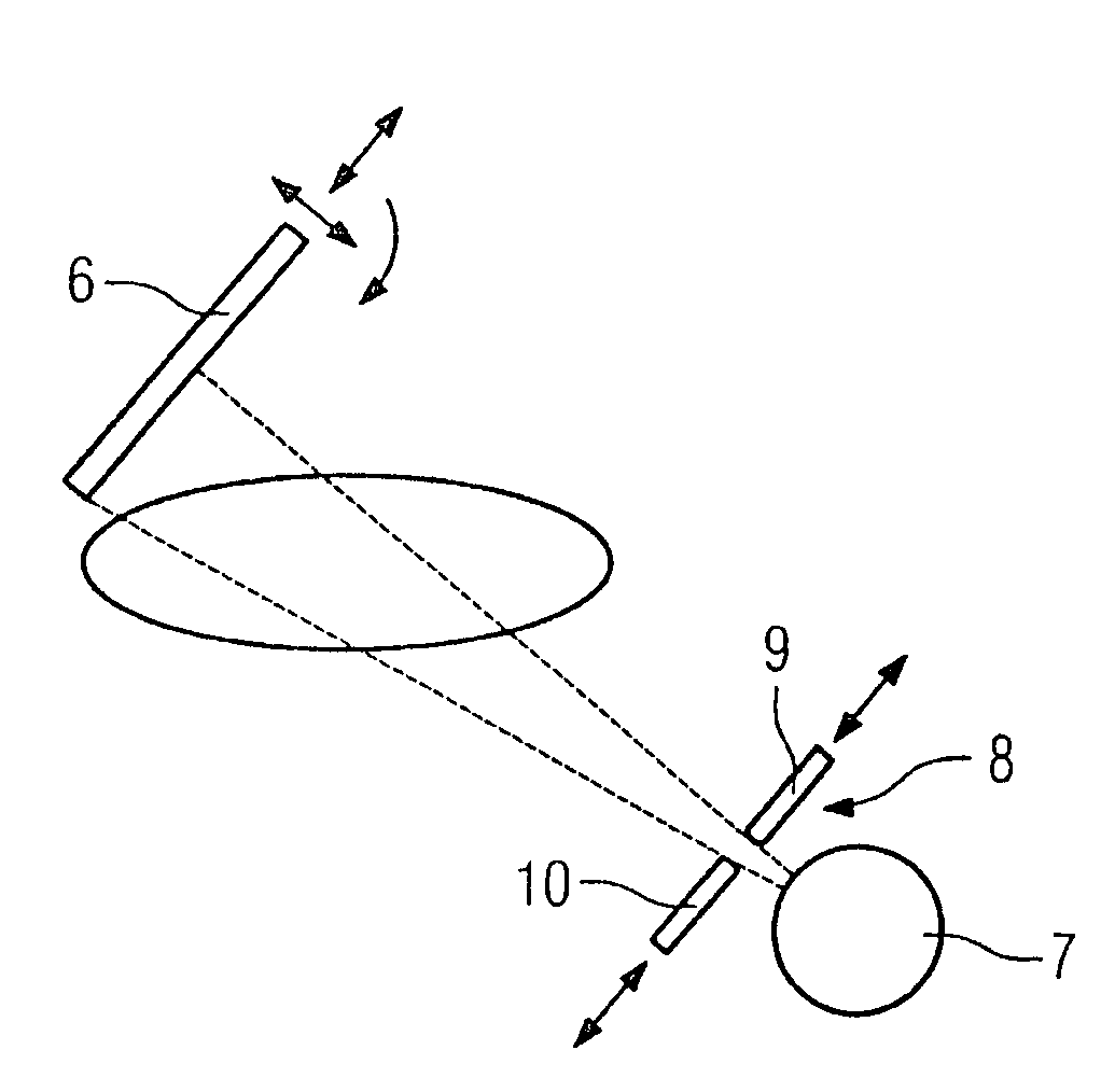
[0024]FIG. 2 shows an exemplary embodiment of the invention, whereby certain components of the X-ray device, which are of no significance for the invention, are not displayed. The detector 6 can be asymmetrically controlled and read out. It is possible to read out only subareas of the detector, so that the...


PUM


Abstract

X-ray device with a detector and an adjustable diaphragm for fading-in an examination area, whereby the detector (6) can be controlled and read-out asymmetrically and the diaphragm (8) can be moved asymmetrically.

Description

CROSS REFERENCE TO RELATED APPLICATIONS[0001]This application claims priority to the German application No. 10 2004 004 630.1, filed Jan. 29, 2004 which is incorporated by reference herein in its entirety.FIELD OF INVENTION[0002]The invention relates to an X-ray device, in particular with a C-arm carrier system, with a detector and an adjustable diaphragm for fading-in X-rays onto an examination area.BACKGROUND OF INVENTION[0003]In modern digital X-ray systems, the size of the detector is selected with regard to the main examinations to be carried out. This is why different detectors are used for cardiological applications, fluoroscopy examinations or vascular applications, said detectors differing in terms of their size. One important criterion in selecting the detector size is the ease of access to the patient during the angulation of the C-arm carrier system on the X-ray device. It is not possible to perform certain examinations using a detector of a different size, since in this...

Claims


Application Information

Patent Timeline
Patent Type & Authority Patents(United States)
IPC IPC(8): G21K1/04A61B6/00A61B6/06G21K5/00G21K5/10
CPCA61B6/06A61B6/4441
Inventor GROH, BURKHARDHEER, VOLKERHORNIG, MATHIASSANDKAMP, BERNHARD
Owner SIEMENS HEALTHCARE GMBH
Why Eureka
Try Eureka