Non-Isotropic Structures for Heat Exchangers and Reactors

Active Publication Date: 2012-10-18
ALTEX TECH
View PDF10 Cites 18 Cited by
  • Summary
  • Abstract
  • Description
  • Claims
  • Application Information

AI Technical Summary

Benefits of technology

[0012]As indicated above, high performance compact heat exchangers and reactors need substantial surface area in contact with the fluid. This is typically provided by fins that extend out into the flow and provide extra area that augments heat flow to or from the separating plate, or boundary, that is the heat sink or heat source, respectively. While heat flow is augmented, the design of the fins can constrain the flow of

Problems solved by technology

While heat flow is augmented, the design of the fins can constrain the flow of heat as a result of conduction limits through the fins.
Unless the fin effectiveness can be maintained at high levels, fin area will be excessive, resulting in excessiv

Method used


Image

  • Non-Isotropic Structures for Heat Exchangers and Reactors
  • Non-Isotropic Structures for Heat Exchangers and Reactors
  • Non-Isotropic Structures for Heat Exchangers and Reactors

Examples


Example

[0031]Theory

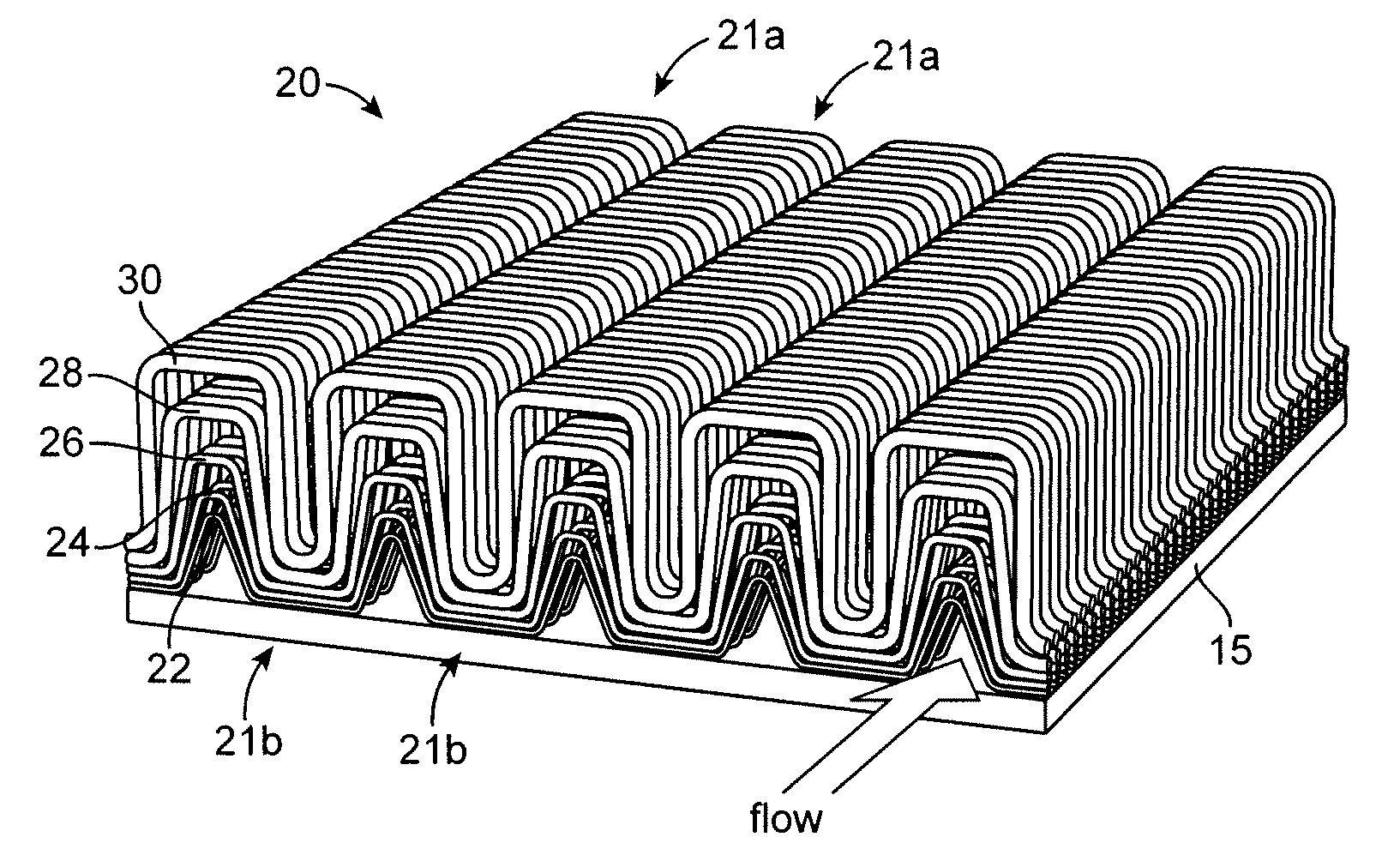
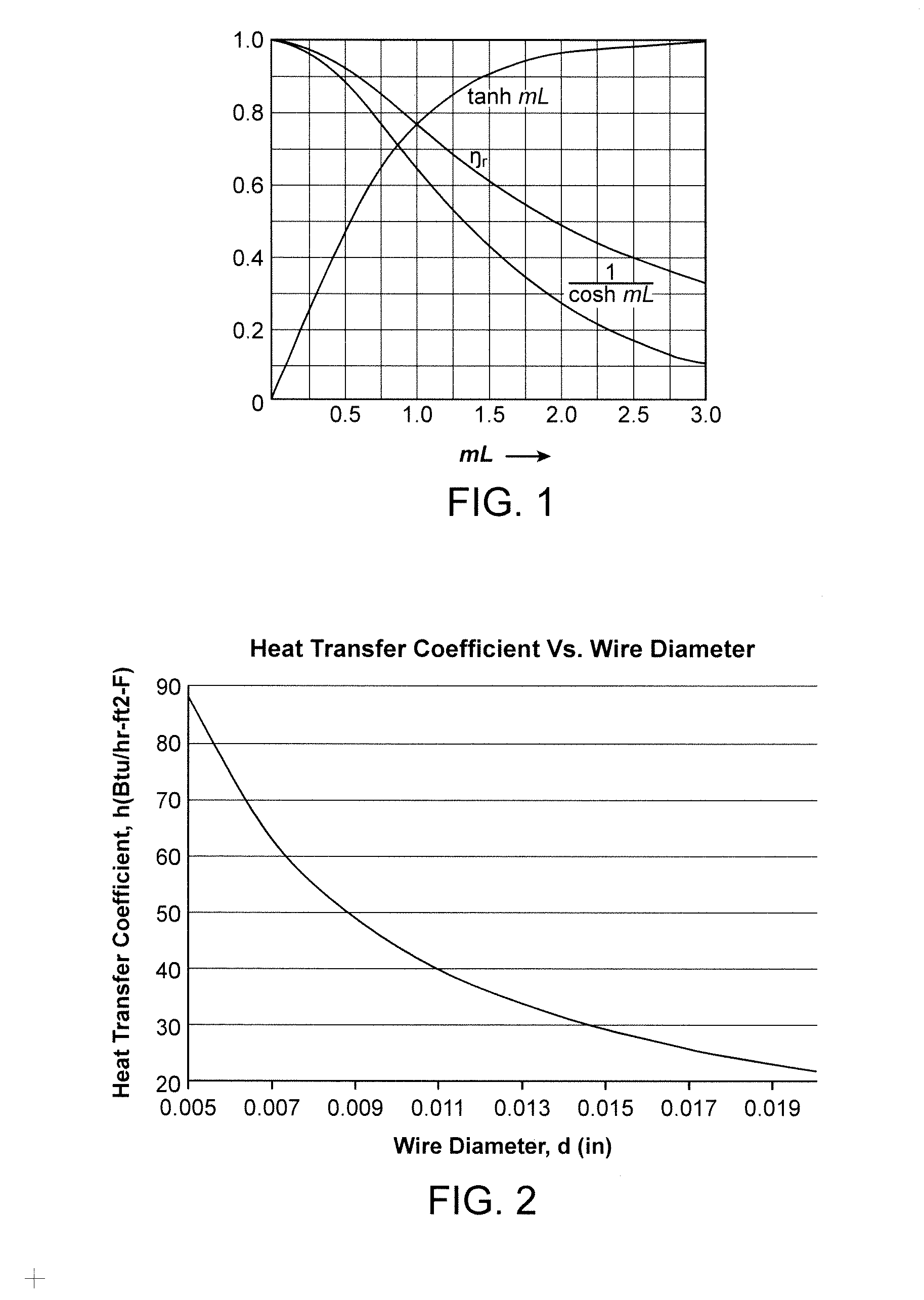
[0032]Through recent investigations of foams and other enhanced heat transfer methods, it has been concluded that a primary limitation of foam is a result of its isotropic nature. Heat transfer from a sink to air has to occur via heat flow from the source through structures that reach out into the air-flow. These structures can be a bottleneck to heat transfer, which is commonly termed “low fin effectiveness”. FIG. 1 presents fin effectiveness results, Nr, as a function of mL, where L is the length of the fin and m is a key parameter defined for a pin fin as m=(4h / kd)1 / 2, where h is the gas heat transfer coefficient, k is the thermal conductivity of the fin material and d is the diameter of the pin.

[0033]As shown in FIG. 1, as the fin length L increases, the effectiveness decreases. This is a measure of the effectiveness of the fin surface area versus the area through which the heat passes to the separation plate and adjoining heat transfer fluid, or primary surface area...


PUM

PropertyMeasurementUnit
Thicknessaaaaaaaaaa
Flow rateaaaaaaaaaa
Diameteraaaaaaaaaa

Abstract

A Non-Isotropic Structure for a Heat Exchanger (NISHEX) that forms fins from nested woven wire meshes. The wire meshes are shaped into channels that are stacked on top of each other to produce a non-isotropic fin structure having multiple fin layers. The fin structure exhibits a high heat coefficient while maintaining relatively high fin efficiency through the selection of fin lengths in proportion to the wire diameter in the mesh fins.

Description

PRIORITY CLAIM[0001]This application claims priority U.S. provisional application No. 61 / 475,116 filed on Apr. 13, 2011 (attorney docket no. 100842.5).FIELD OF THE INVENTION[0002]The present invention relates to heat exchangers and reactors.BACKGROUND OF THE INVENTION[0003]Finned Compact Heat Exchangers.[0004]Heat Exchanger (HEX) size and weight with gas flows are typically limited by the low conductivity of the gas and resulting lower gas side heat transfer coefficients. In these cases, the surface area of plates that separate the fluids, or bound the source of heat (e.g. electronics component) or cooling, is insufficient to meet performance requirements. Fins are added to the separating plate, or primary surface area, to add surface area and reach out into the gas flow. This facilitates the flow of heat from the gas to the separating plate. Fins can increase surface area exposed to the gas by multiple factors. In fact, in some examples, fins represent over 80% of the available sur...

Claims


Application Information

Patent Timeline
IPC IPC(8): F28F7/00B21D53/02
CPCY10T29/4935F28F3/022
Inventor KELLY, JOHN T.
Owner ALTEX TECH
Why Eureka
Try Eureka