
Earphone device

a technology for earphones and earphone cables, which is applied in the direction of earpiece/earphone manufacture/assembly, earpiece/earphone cables, electrical transducers, etc., can solve the problems of insufficient air state, difficulty in maintaining the fitting state, and insufficient bass sound output, so as to improve the comfort of use, the effect of wide housing width and high sound quality

Active Publication Date: 2012-10-25
SONY CORP
View PDF8 Cites 7 Cited by
  • Summary
  • Abstract
  • Description
  • Claims
  • Application Information

AI Technical Summary

Benefits of technology

The present invention provides an earphone device that provides comfortable fitting and high-quality sound. The earphone device includes a housing with a driver unit and a sound guide tube mounted on the front surface of the housing. The sound guide tube is disposed at a position deviated from the center position of the housing. This configuration allows for a larger width of the housing without the housing abutting on the tragus. As a result, the aperture of the diaphragm disposed in the driver unit may increase in size, providing high-quality sound with improved fitting comfortability for the user.

Problems solved by technology

Accordingly, a compression state of air may not vary sufficiently, and hence, the bass sound may not be output effectively.
However, when the earphone device 35 fits in the user's ear, the housing 36 may abuts on the tragus 22, and hence, it is difficult to maintain the fitting state, and even to insert the earphone device 35 to the ear.
With the earplug type earphone device 30, the size of the diaphragm tends to be restricted for improving the fitting state, resulting in difficulty of providing sufficiently high-quality sound.
Contrary, fitting comfortability may be deteriorated if the diaphragm increases in size.

Method used


Image

  • Earphone device
  • Earphone device
  • Earphone device

Examples


Embodiment Construction

[0039]An embodiment of the present invention will be described below with reference to the attached drawings.

1. External Configuration of Earphone Device

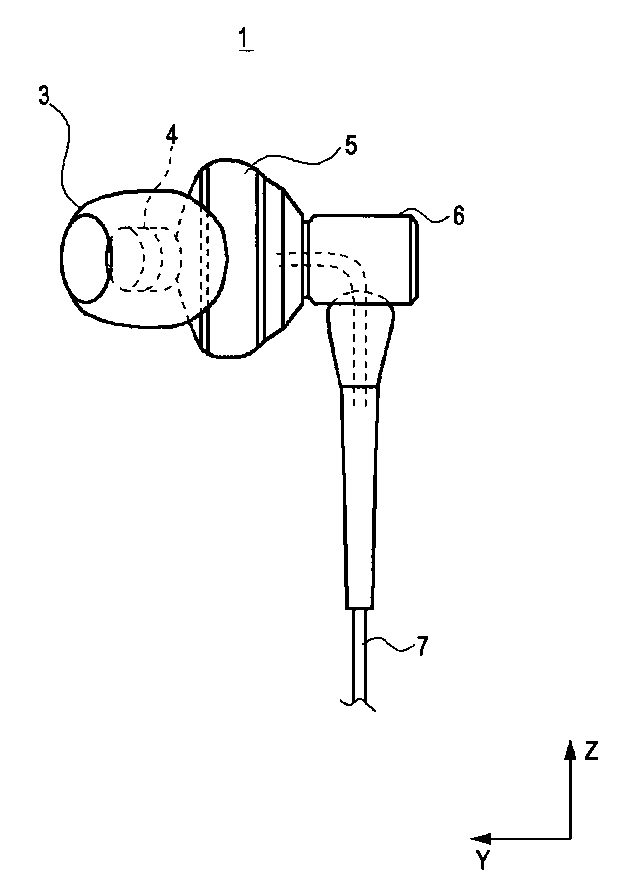
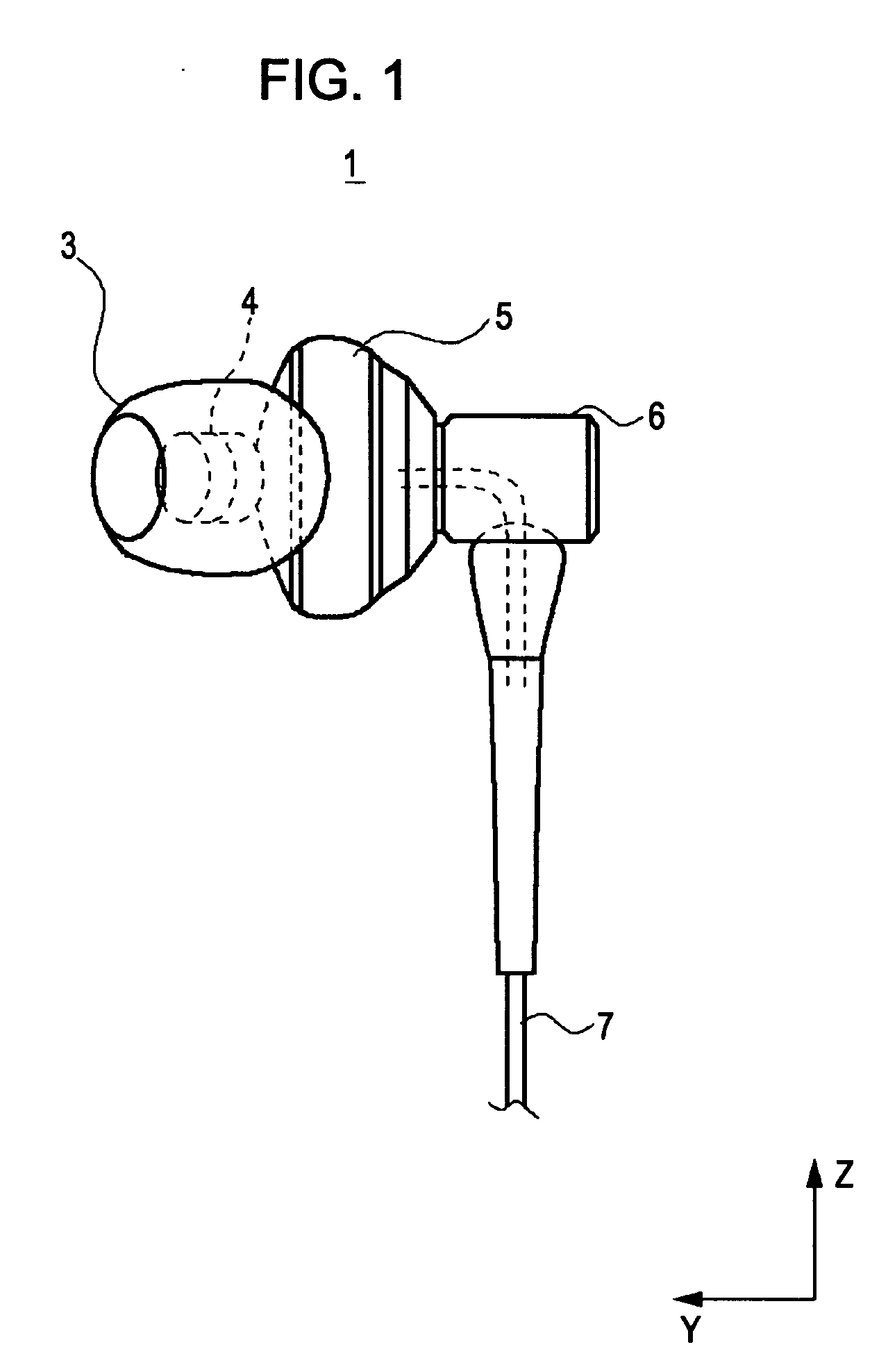
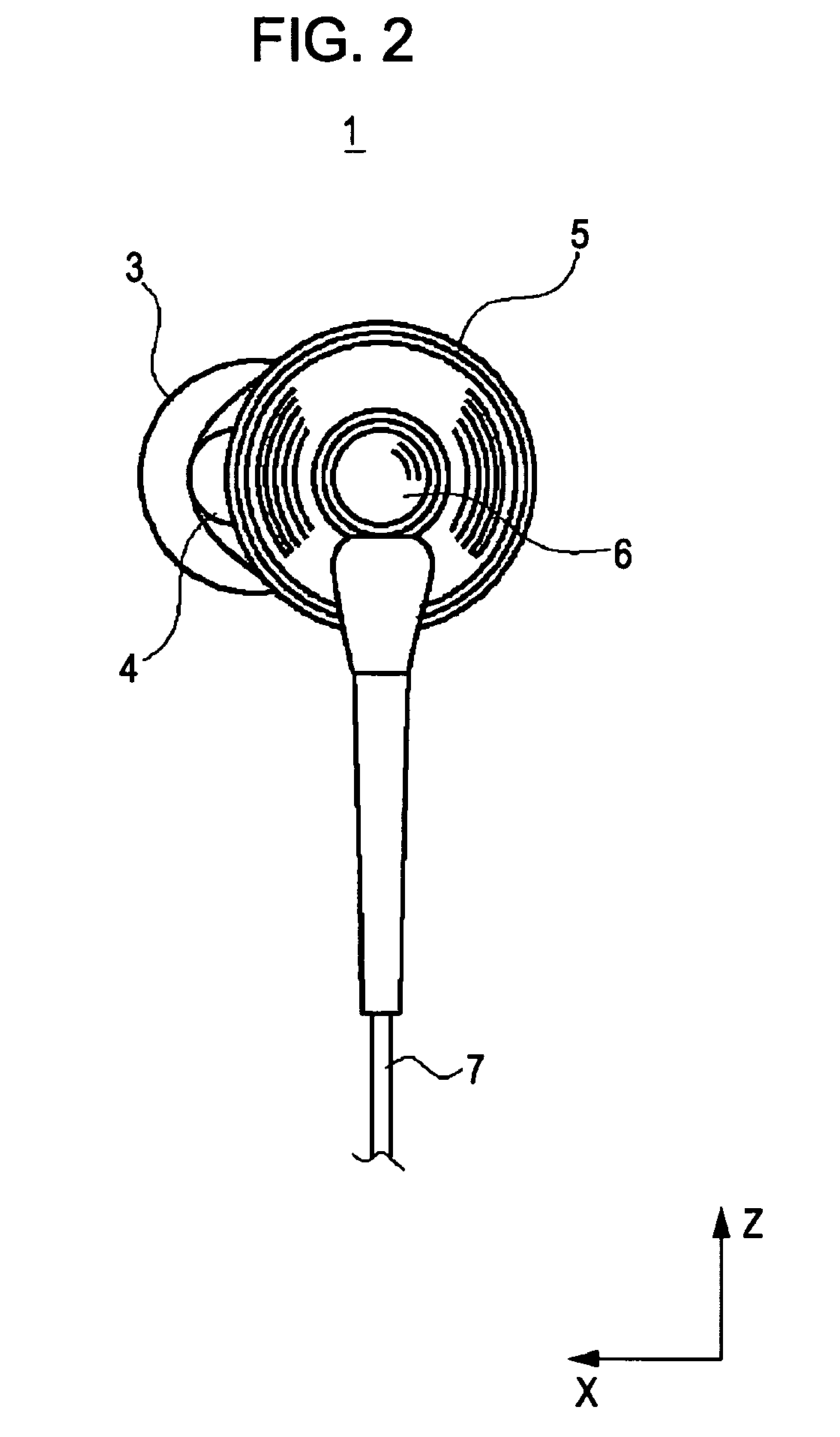
[0040]In FIGS. 1 to 3, an earphone device 1 according to an embodiment of the present invention is shown. The earphone device 1 includes an earpiece 3 having a shape corresponding to an external auditory meatus of a user in a fitting state, a substantially cylindrical sound guide tube 4 provided in the earpiece 3, a substantially spherical housing 5 in which the sound guide tube 4 is mounted, a substantially cylindrical cord retainer 6 integrally provided with the housing 5, and a cord 7 connected to a driver unit disposed in the housing 5.

[0041]FIG. 1 is a lateral elevational view showing the earphone device in the Y-Z plane. FIG. 2 is a rear elevational view showing the earphone device 1 in the X-Z plane. FIG. 3 is a bottom plan view showing the earphone device 1 in the X-Y plane.

[0042]As shown in FIG. 1, the earphone device 1 vib...


PUM


Abstract

An earphone device includes a housing having a driver unit, and a sound guide tube mounted on a front surface of the housing to protrude from the front surface, in which the sound guide tube is disposed at a position deviated from a center position of the housing.

Description

CROSS REFERENCES TO RELATED APPLICATIONS[0001]The present invention contains subject matter related to Japanese Patent Application JP 2006-005412 filed in the Japanese Patent Office on Jan. 12, 2006, the entire contents of which are incorporated herein by reference.BACKGROUND OF THE INVENTION[0002]1. Field of the Invention[0003]The present invention relates to earphone devices. For example, the present invention may be applied to an earplug type earphone device in which a sound tube is inserted to an external auditory meatus with an earpiece interposed therebetween.[0004]2. Description of the Related Art[0005]An earphone device typically vibrates a diaphragm disposed in a driver unit accommodated in a housing (a casing of the earphone device) in accordance with audio signals supplied from a portable music player or the like, varies a compression state of air, and thus generates sound corresponding to the audio signals.[0006]For example, according to a lateral in-the-ear earphone dev...

Claims


Application Information

Patent Timeline
Patent Type & Authority Applications(United States)
IPC IPC(8): H04R1/10
CPCH04R1/1016H04R1/345H04R1/1066H04R1/1091H04R1/10H04R29/001H04R1/1008H04R1/02H04R1/1058H04R2499/11H04R1/1033H04R1/2807H04R1/34
Inventor MATSUO, TOMOHIROOHTA, TAKASHINAGENO, KOJIITO, TOMOHIRO
Owner SONY CORP
Learn More