Fluid quality sensor

Active Publication Date: 2012-11-15
PANASONIC INTELLECTUAL PROPERTY MANAGEMENT CO LTD
View PDF32 Cites 1 Cited by
  • Summary
  • Abstract
  • Description
  • Claims
  • Application Information

AI Technical Summary

Benefits of technology

[0014]According to the present invention, the plurality of points of the internal electrode in the direction of the passage are supported by the casing via the supporting members such that the internal electrode is he

Problems solved by technology

However, the increased distance between electrodes inevitably reduces the detection accuracy.
Further, the cross-sectional area of the fluid path becomes non-uniform and the flow o

Method used


Image

  • Fluid quality sensor
  • Fluid quality sensor
  • Fluid quality sensor

Examples


first embodiment

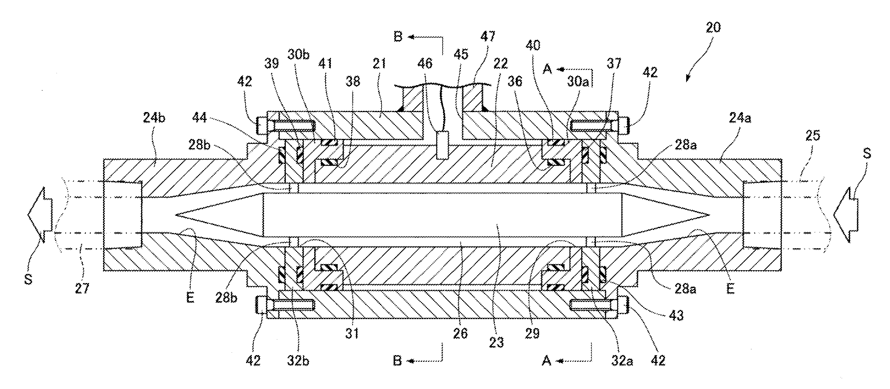
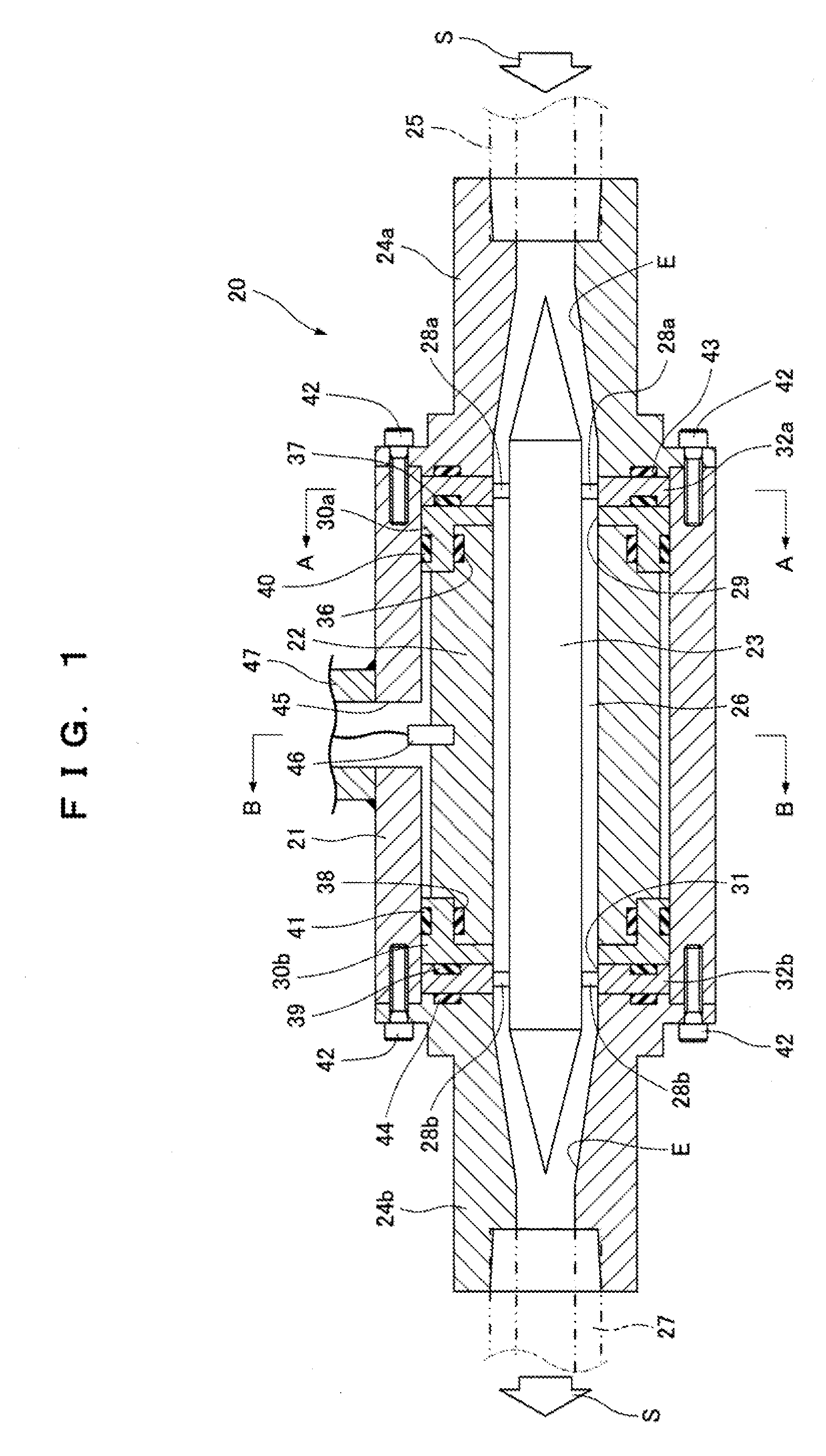
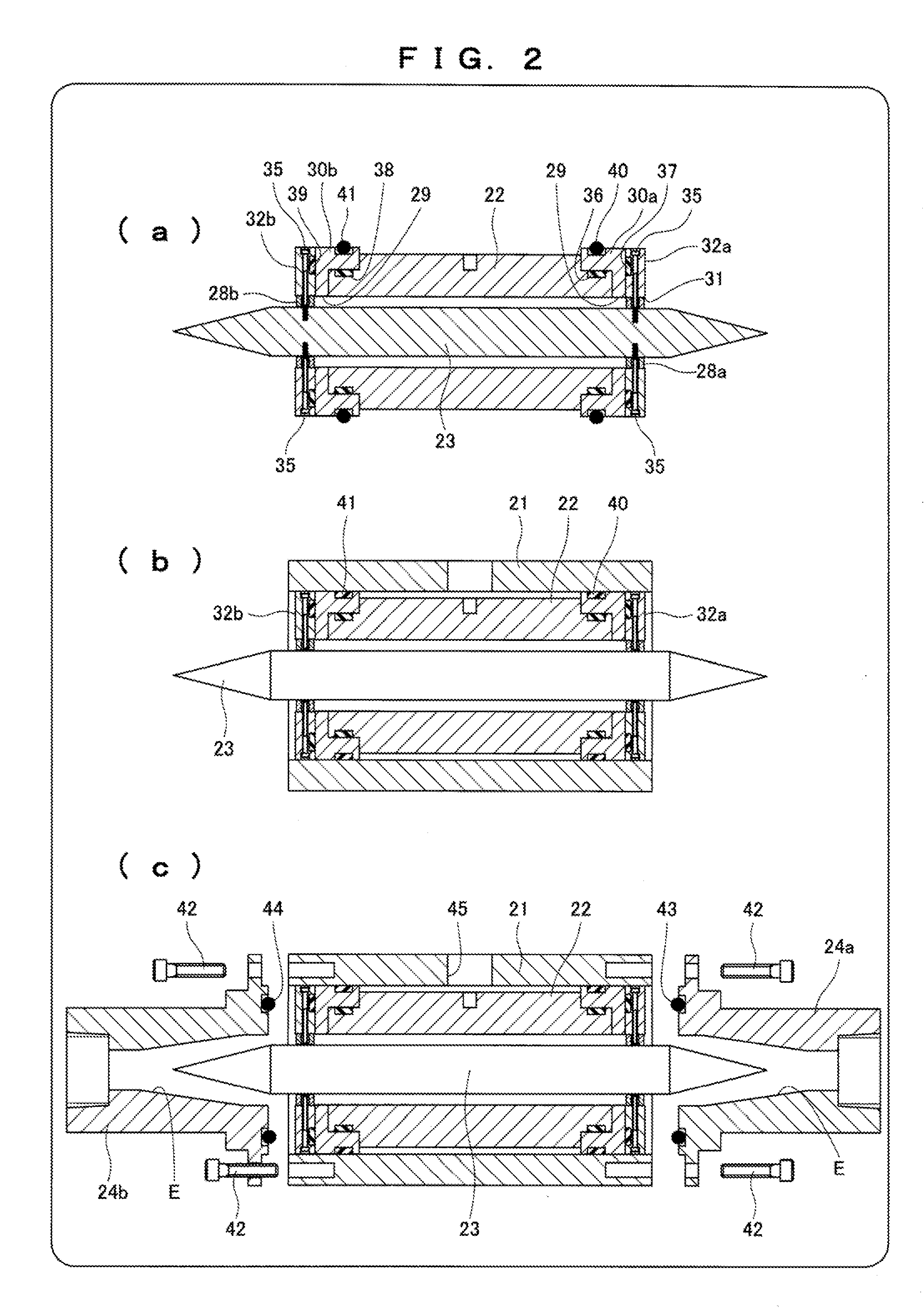
[0028]FIGS. 1 to 5 show a fluid quality sensor 20 according to a first embodiment.

[0029]The fluid quality sensor 20 includes: a tubular casing 21; a tubular external electrode 22 fixed to the inner side of the casing 21; an internal electrode 23 disposed on the inner side of the external electrode 22 coaxially with the external electrode 22; and adapters 24a and 24b attached to ends of the casing 21. A fluid S flows into the fluid quality sensor 20 from a fluid pipe 25 connected to the adapter 24a.

[0030]The fluid S having flowed into the fluid quality sensor 20 passes through a detection passage 26 formed between the inner circumference of the external electrode 22 and the outer periphery of the internal electrode 23 and flows out of a fluid pipe 27 connected to the adapter 24b via the adapter 24b.

[0031]The internal electrode 23 having two cone-shaped ends is supported by the casing 21 via supporting members 28a and 28b at multiple points, in this embodiment, at two points in the ...

example 1

[0051]FIG. 6 shows a specific example of the fluid quality sensor 20 placed in the material supply piping of urethane foaming equipment for refrigerator insulation.

[0052]The equipment includes: circulating material supply piping containing a premix material 53 having a second material 52 (cyclopentane) acting as a foaming agent mixed in a first material 51 (polyol component); circulating material supply piping containing a third material 54 (isocyanate component); and a mixing head 55 which mixes and discharges the materials. The equipment is production equipment which injects an urethane raw material into a thermally-insulated housing of a refrigerator or the like.

[0053]A liquid-liquid mixer 56 typified by a static mixer is used for mixing the first material 51 and the second material 52. Since the second material acting as a foaming agent is cyclopentane in the production equipment, the fluid quality sensor 20 of the production equipment conforms to the specification of intrinsic ...

example 2

[0061]FIG. 8 is different from FIG. 6 in that a foaming agent 57 (carbon dioxide) having a boiling point of 0° C. or lower at substantially atmospheric pressure is mixed on the upstream side of the mixing head 55. The mixed path is disclosed by Japanese Patent Application Laid-Open Publication No. 2010-1038239. The fluid quality sensor 20 is interposed on the subsequent stage of a liquid-liquid mixer 58. Others are the same as those in FIG. 6.

[0062]The newly-mixed foaming agent 57 evaporates at substantially atmospheric pressure, and thus generates air bubbles in the premix material 53. Hence, the liquid-liquid mixer 58, and so on are desirably used in a high-pressure ambience of about 8 MPa to 13 MPa. The premix material 53 and the foaming agent 57 are mixed by the liquid-liquid mixer 58, are then mixed with the third material 54 by the mixing head 55, and are discharged out of the system. Since the discharged materials contain the foaming agent 57 which easily evaporates at substa...


PUM


Abstract

An object of the present invention is to accurately detect concentrations of mixtures in a fluid. An internal electrode 23 is disposed on the inner side of an external electrode 22 coaxially with the external electrode 22, and a plurality of points in the length direction of the internal electrode 23 are supported by a casing 21 via supporting members 28a and 28b. The state of a fluid S passing through a passage 26 between the external electrode 22 and the internal electrode 23 is detected based on electrostatic capacitance between the external electrode 22 and the internal electrode 23.

Description

FIELD OF THE INVENTION [0001]The present invention relates to a fluid quality sensor for detecting the concentration of a fluid by a capacitive sensing method.BACKGROUND OF THE INVENTION[0002]FIG. 11 shows a fluid quality sensor of WO2007 / 019577. In order that a fluid S flowing from an upstream fluid pipe 25 toward a downstream fluid pipe 27 may be detected based on electrostatic capacitance and temperature, a pipe 61 connected to the fluid pipe 25, a pipe 62 connected to the fluid pipe 27, and an intermediate pipe 63 interposed between the pipes 61 and 62 form a fluid path 64. An internal electrode 65 is disposed on the fluid path 64 inside the immediate pipe 63 via a supporting member 66. The intermediate pipe 63 is an external electrode, and the internal electrode 65 is electrically insulated from the immediate pipe 63 by the supporting member 66. A temperature sensor 67 indirectly detects the temperature of the internal electrode 65 with a detector 68 thermally connected to the ...

Claims


Application Information

Patent Timeline
IPC IPC(8): G01R27/26
CPCG01N27/226
Inventor TSURUTA, TAKASHINISHIKAWA, KAZUHIROKUBOTA, KOICHISHIBAYAMA, TAKUTO
Owner PANASONIC INTELLECTUAL PROPERTY MANAGEMENT CO LTD
Why Eureka
Try Eureka