Conduit sensor device with magnetic shunt and process for modifying a magnetic field

a sensor device and magnetic shunt technology, applied in the direction of magnetic properties, magnetic measurements, instruments, etc., can solve the problems of difficult control of magnetic field, ineffective shunting of magnetic field produced by the poles, etc., and achieve the effect of reducing magnetic field and drawing more easily through the pipelin

Active Publication Date: 2012-11-22
INVODANE ENG
View PDF1 Cites 5 Cited by
  • Summary
  • Abstract
  • Description
  • Claims
  • Application Information

AI Technical Summary

Benefits of technology

[0009]Each conduit sensor device includes a magnetic shunt device. The magnetic shunt device is used effectively turns off the magnetic field. The inspection pig is propelled through the pipeline / conduit by drive means which are not shown. Each of the conduit sensor devices are connected to the drive means. Further, and importantly, the magnetic shunt device enables the curtailment of the magnetic field in the pipeline / conduit making movement of the inspection pig within the interior of the pipeline / conduit and through valves and other obstructions inside the pipeline easier. As stated above the inspection pig is driven by drive means not shown.
[0021]The first rotor gear rotates the first rotor shunt and the first rotatable magnet between 0° and 180° synchronously with the second rotor gear rotating the second rotor shunt and the second rotatable magnet between 0° to 180°. Positioning of the first and second rotatable magnets between the respective permanent magnets moderates the magnetic field located between the first and the second magnetic poles.
[0029]It is a further object of the invention to substantially cancel the magnetic field between the poles of the device so that the device may be drawn more easily through the pipeline as the sensor and its supporting structure are no longer magnetically attracted to the walls of the conduit / pipeline.
[0034]It is a further object of the invention to mechanically prevent the over travel of the rotor shunts and the rotatable magnets of the pipeline inspection device.

Problems solved by technology

U.S. Pat. No. 6,762,602 to Laursen et al. does not effectively shunt the magnetic field produced by the poles through use of respective rotatable magnets.
Further, a spring is necessary for each of the rotatable magnets and adjustment of those magnets in a coordinated manner is difficult, and, therefore, control of the magnetic field is difficult.
One of the poles in the Laursen '602 patent may be adjusted differently than the other pole because the springs and toothed gears cannot be matched or properly controlled.
However, there is no disclosure in Laursen as to the coordinated operation and control of the rotatable magnets.

Method used


Image

  • Conduit sensor device with magnetic shunt and process for modifying a magnetic field
  • Conduit sensor device with magnetic shunt and process for modifying a magnetic field
  • Conduit sensor device with magnetic shunt and process for modifying a magnetic field

Examples


Embodiment Construction

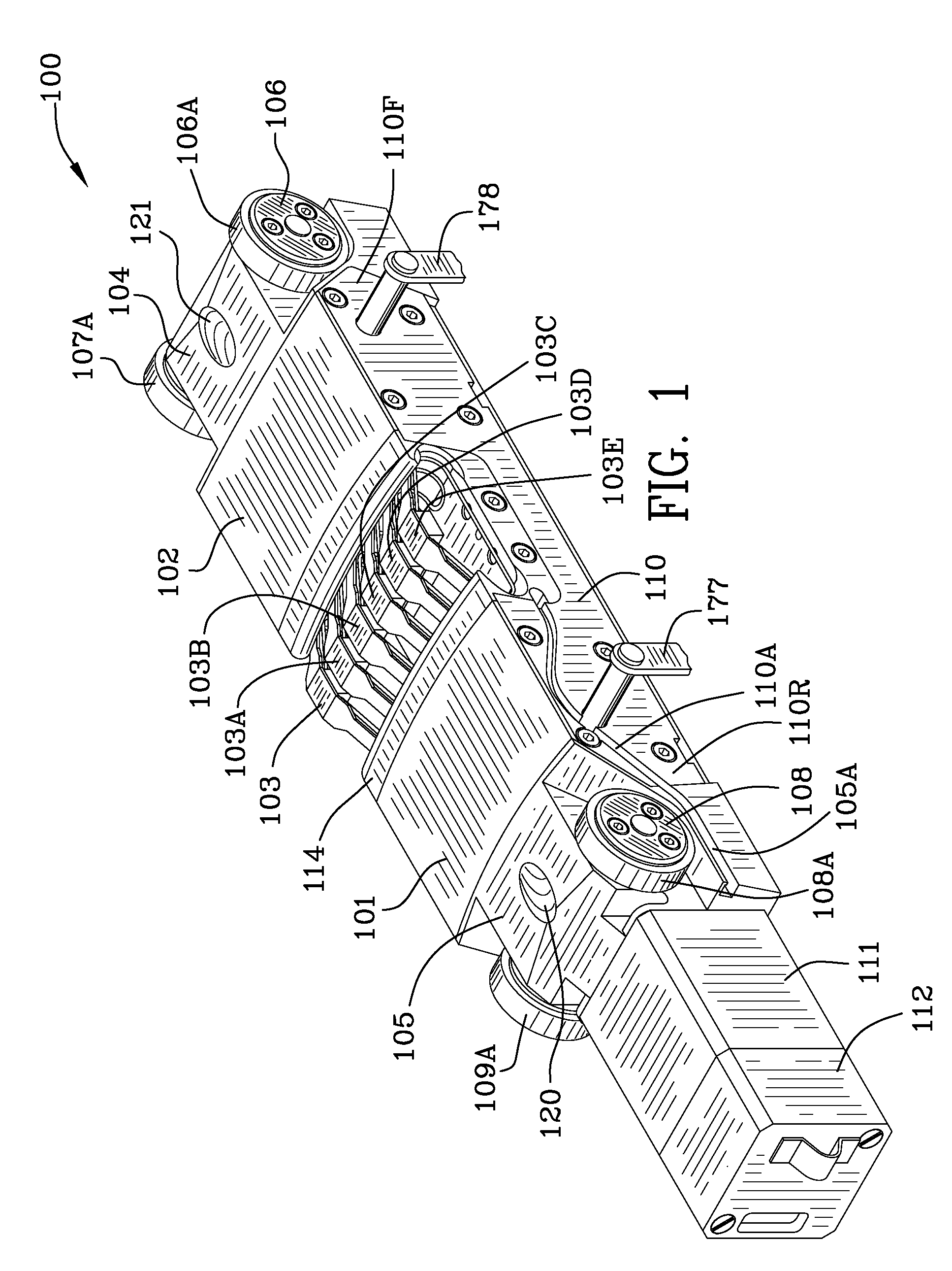
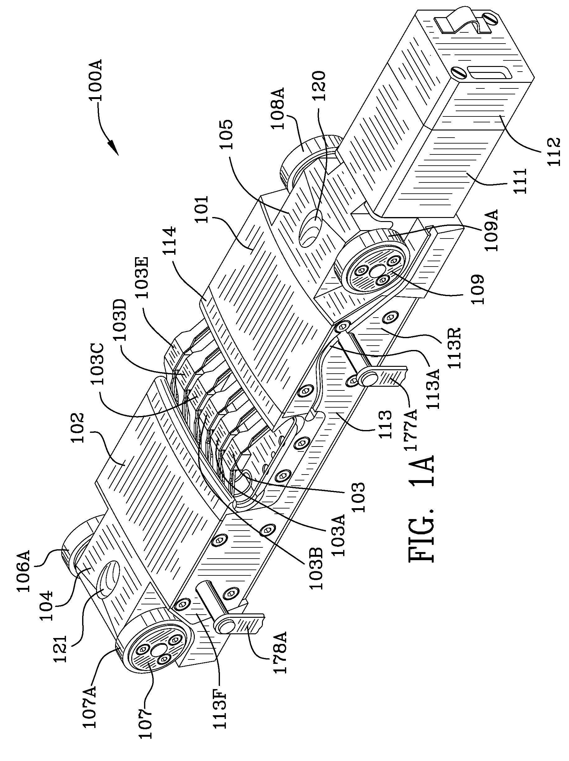
[0086]FIG. 1 is a perspective view 100 of the conduit sensor device including a magnetic shunt illustrating the aft pole 101, the forward pole 102, and sensors 103, 103A, 103B, 103C, 103D, 103E for detecting anomalies or variations in a conduit / pipeline. The conduit sensor which includes the magnetic shunt device shown and described herein is one of a plurality of such devices located about the inner periphery of the pipeline / conduit.

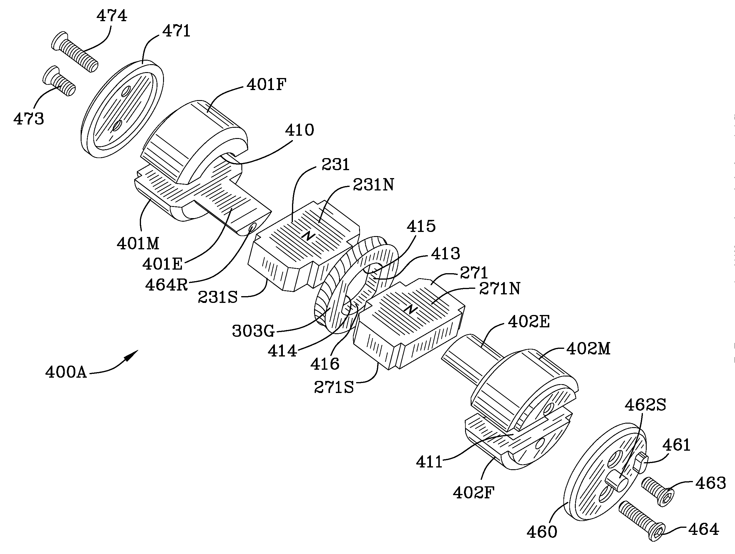
[0087]Poles 101, 102 are manufactured from 1018 steel. A magnetic field is created by sets of magnets beneath poles 101, 102. A first set (aft set) of magnets comprises rare earth permanent magnets 230, 232 and rare earth rotatable magnets 231, 271. A second set of magnets comprises rare earth magnets 240, 242 and rare earth rotatable magnets 241, 281. The rare earth magnets are NdFeB magnets. Other rare earth magnets may be used. Magnets other than rare earth magnets may be used. The device 100 is capable of modifying and / or substantially cancelling th...


PUM

PropertyMeasurementUnit
angleaaaaaaaaaa
magnetic fieldaaaaaaaaaa
strengthaaaaaaaaaa

Abstract

A conduit sensor device includes first and second pairs of permanent magnets. First and second rotor shunts include first and second rotatable magnets and interposed between the first and second pairs of permanent magnets, respectively. A shunt shaft includes a first helical worm gear and a second helical worm gear mounted thereon. The first rotor shunt includes a first rotatable magnet and a first rotor gear locked together. The first helical worm gear meshing with the first rotor gear driving the first rotor gear and the first rotatable magnet. The second rotor shunt includes a second rotatable magnet and a second rotor gear locked together. The second helical worm gear meshes with the second rotor gear driving the second rotor gear and the second rotatable magnet. The surface areas of the first and second pairs of permanent magnets equals the surface area of the first and second rotatable magnets.

Description

FIELD OF THE INVENTION[0001]The invention is in the field of pipeline inspection devices / sensors.BACKGROUND OF THE INVENTION[0002]U.S. Pat. No. 6,762,602 to Laursen et al. proposed a “device, e.g. an inspection pig, for inspecting conduits made from ferromagnetic materials, such as pipelines, for faults, cracks, corrosion or the like, comprising at least one pulling element, a supporting structure of variable circumference, disposed on the pulling element and comprising substantially radially disposed supporting arms each of which is pivotable about axes disposed perpendicular to the longitudinal central axis of the pulling element, and several permanent magnets disposed at the circumference of the supporting structure for generating a magnetic filed, and with sensors.” Further, Laursen, states: “[f] or strengthening or weakening the magnetic field generated by the permanent magnet in dependence on the circumference of the supporting structure or in dependence on the lateral separat...

Claims


Application Information

Patent Timeline
Patent Type & Authority Applications(United States)
IPC IPC(8): G01N27/82H01F7/02
CPCG01N2291/2636G01N27/82
Inventor LAURSEN, PAULCOMELLO, CORRYLEE, RODERICK
Owner INVODANE ENG
Why Eureka
Try Eureka