Conduit sensor device propulsion apparatus and process for operating the propulsion apparatus

a sensor device and propulsion apparatus technology, applied in the direction of measurement devices, elasticity measurement, instruments, etc., can solve the problems of difficult control of magnetic field, ineffective shunting of magnetic field produced by the poles, etc., and achieve the effect of maximum strength magnetic field

Active Publication Date: 2014-01-16
INVODANE ENG
View PDF1 Cites 2 Cited by
  • Summary
  • Abstract
  • Description
  • Claims
  • Application Information

AI Technical Summary

Benefits of technology

[0011]Each conduit sensor device includes a magnetic shunt device. The magnetic shunt device is used to effectively turn off the magnetic field. The inspection pig is propelled through the pipeline / conduit by drive means which are disclosed herein. Each of the conduit sensor devices propels the conduit sensor device through the pipeline to be inspected. Further, and importantly, the magnetic shunt device enables the curtailment of the magnetic field in the pipeline / conduit making movement of the inspection pig within the interior of the pipeline / conduit and through valves and other obstructions inside the pipeline easier.

Problems solved by technology

U.S. Pat. No. 6,762,602 to Laursen et al. does not effectively shunt the magnetic field produced by the poles through use of respective rotatable magnets.
Further, a spring is necessary for each of the rotatable magnets and adjustment of those magnets in a coordinated manner is difficult, and, therefore, control of the magnetic field is difficult.
One of the poles in the Laursen '602 patent may be adjusted differently than the other pole because the springs and toothed gears cannot be matched or properly controlled.
However, there is no disclosure in Laursen as to the coordinated operation and control of the rotatable magnets.

Method used


Image

  • Conduit sensor device propulsion apparatus and process for operating the propulsion apparatus
  • Conduit sensor device propulsion apparatus and process for operating the propulsion apparatus
  • Conduit sensor device propulsion apparatus and process for operating the propulsion apparatus

Examples


Embodiment Construction

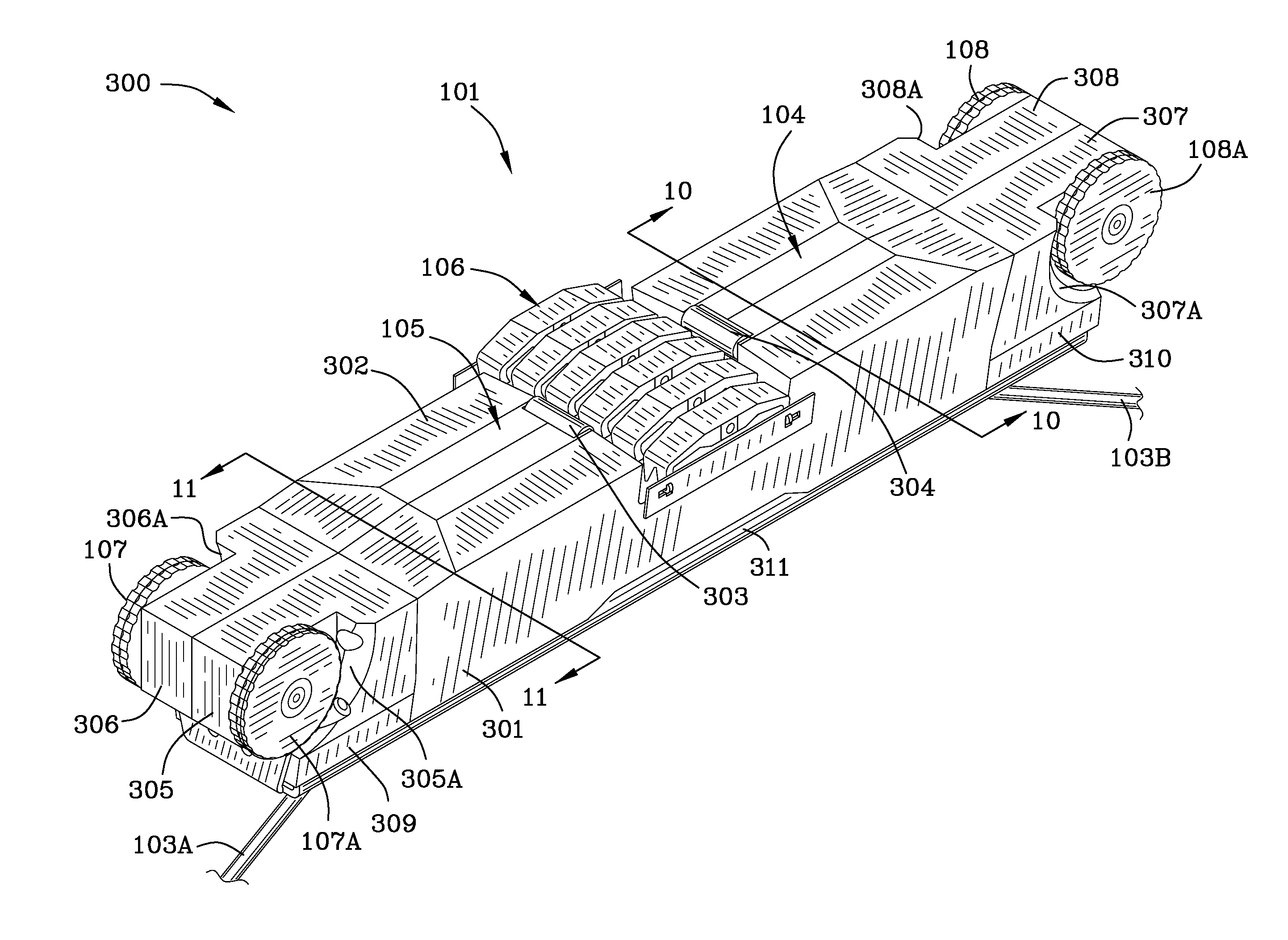
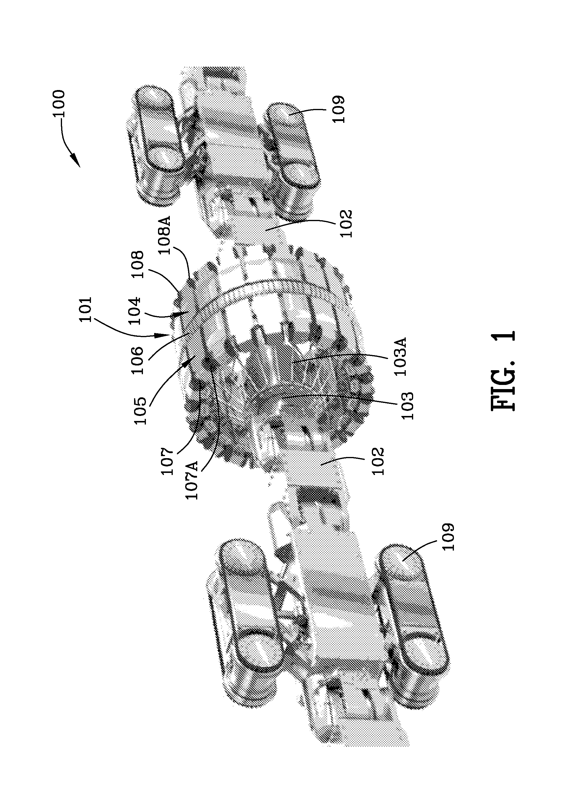
[0080]FIG. 1 is a schematic perspective view 100 of a plurality of conduit sensor devices 101, and, each of the conduit sensor devices 101 includes a plurality of sensors 106 and magnetic shunts. Arrow 101 is illustrated pointing to one conduit sensor with a magnetic shunt therein. Reference numeral 102 is used to denote couplings between the plurality of conduit sensors and battery powered drive units 109. A tubular radial control mechanism 103 controls wires / rods for extending the conduit sensors 101 radially outwardly and for contracting the conduit sensors radially inwardly. Arrow 104 indicates the second end of one conduit sensor with a magnetic shunt and arrow 105 indicates the first end of one conduit sensor with magnetic shunt. Arrow 106 indicates electronic sensors used to detect anomalies and defects in pipes and conduits. Reference numerals 107, 107A, 108, 108A denote rubber / synthetic propulsion wheels.

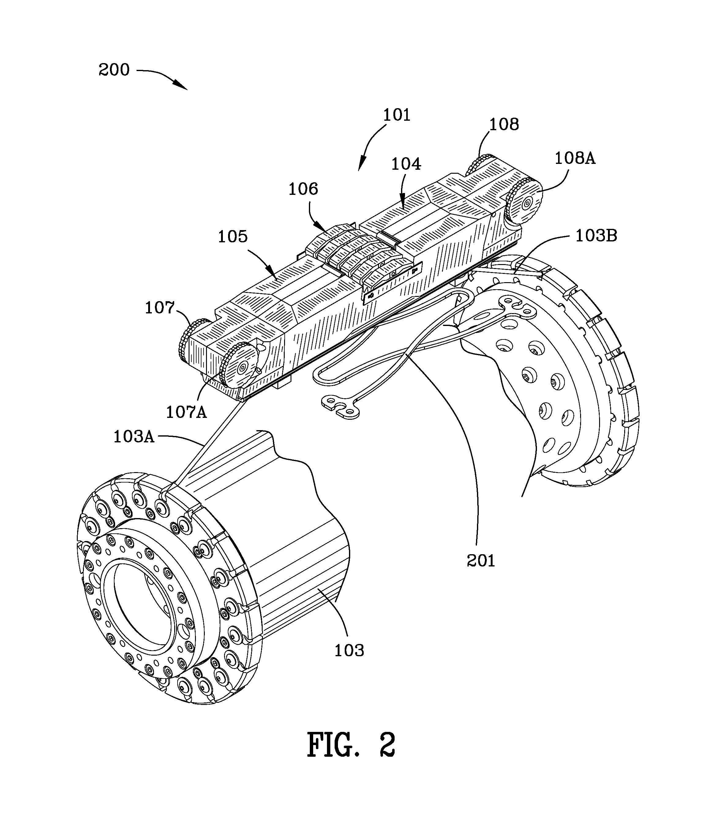
[0081]FIG. 2 is an enlargement 200 of a portion of FIG. 1 illustrating...


PUM

PropertyMeasurementUnit
angleaaaaaaaaaa
helix angleaaaaaaaaaa

Abstract

A conduit sensor device comprises a first end portion, a second end portion, a first magnet rotor assembly residing proximate the first end portion of the device and rotatable between first and second positions, a second magnet rotor assembly residing proximate the second end portion of the device and rotatable between first and second positions. The first magnet rotor assembly includes a first plurality of magnets axially arranged about a first axis. The first magnet rotor assembly includes a first top portion and a first bottom portion securing the first plurality of magnets within the first magnet rotor assembly. The second magnet rotor assembly includes a second plurality of magnets axially arranged about a second axis. The second magnet rotor assembly includes a second top portion and a second bottom portion securing the second plurality of magnets within the second magnet rotor assembly.

Description

[0001]U.S. patent application Ser. No. 12 / 836,230 filed Jul. 14, 2010 is hereby incorporated by reference herein in its entirety by reference hereto the same as if written herein verbatim.FIELD OF THE INVENTION[0002]The invention is in the field of pipeline inspection devices / sensors.BACKGROUND OF THE INVENTION[0003]U.S. Pat. No. 6,762,602 to Laursen et al. proposed a “device, e.g. an inspection pig, for inspecting conduits made from ferromagnetic materials, such as pipelines, for faults, cracks, corrosion or the like, comprising at least one pulling element, a supporting structure of variable circumference, disposed on the pulling element and comprising substantially radially disposed supporting arms each of which is pivotable about axes disposed perpendicular to the longitudinal central axis of the pulling element, and several permanent magnets disposed at the circumference of the supporting structure for generating a magnetic filed, and with sensors.” Further, Laursen, states, pe...

Claims


Application Information

Patent Timeline
Patent Type & Authority Applications(United States)
IPC IPC(8): G01N33/00
CPCG01N27/82G01N2291/2636G01M5/0025G01M5/0033G01N35/0099
Inventor LAURSEN, PAULCOMELLO, CORRY
Owner INVODANE ENG
Why Eureka
Try Eureka