

Modular Firearm
- Summary
- Abstract
- Description
- Claims
- Application Information
AI Technical Summary
Problems solved by technology
Method used
Image

Examples
Embodiment Construction
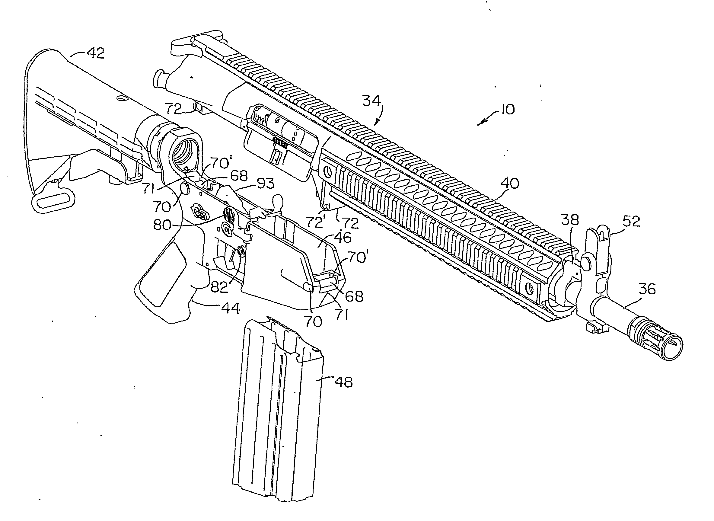
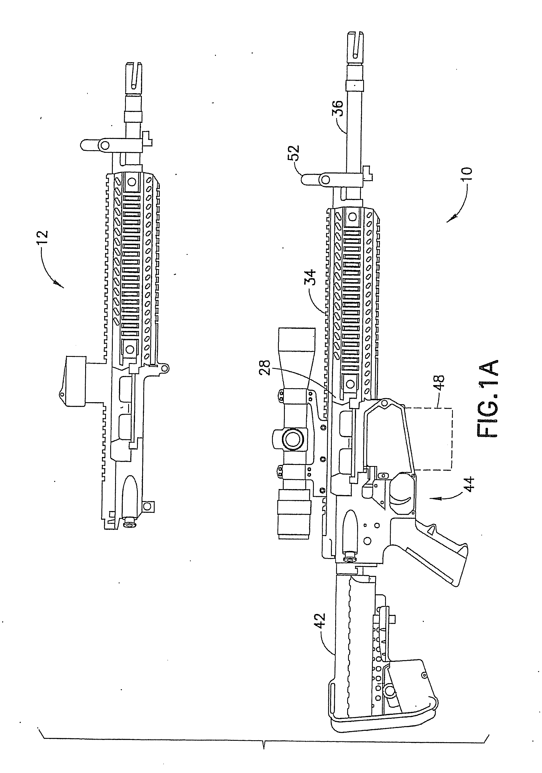
[0056]Referring to FIG. 1A, there is shown, a side elevation view of an automatic or semi-automatic firearm 10 capable of automatic or semiautomatic fire incorporating features in accordance with an exemplary embodiment of the present invention. Although the features of such embodiments will be described with reference to the embodiments shown in the drawings, it should be understood that the described features can be embodied in many alternate forms of embodiments. In addition, any suitable size, shape or type of elements or materials could be used.
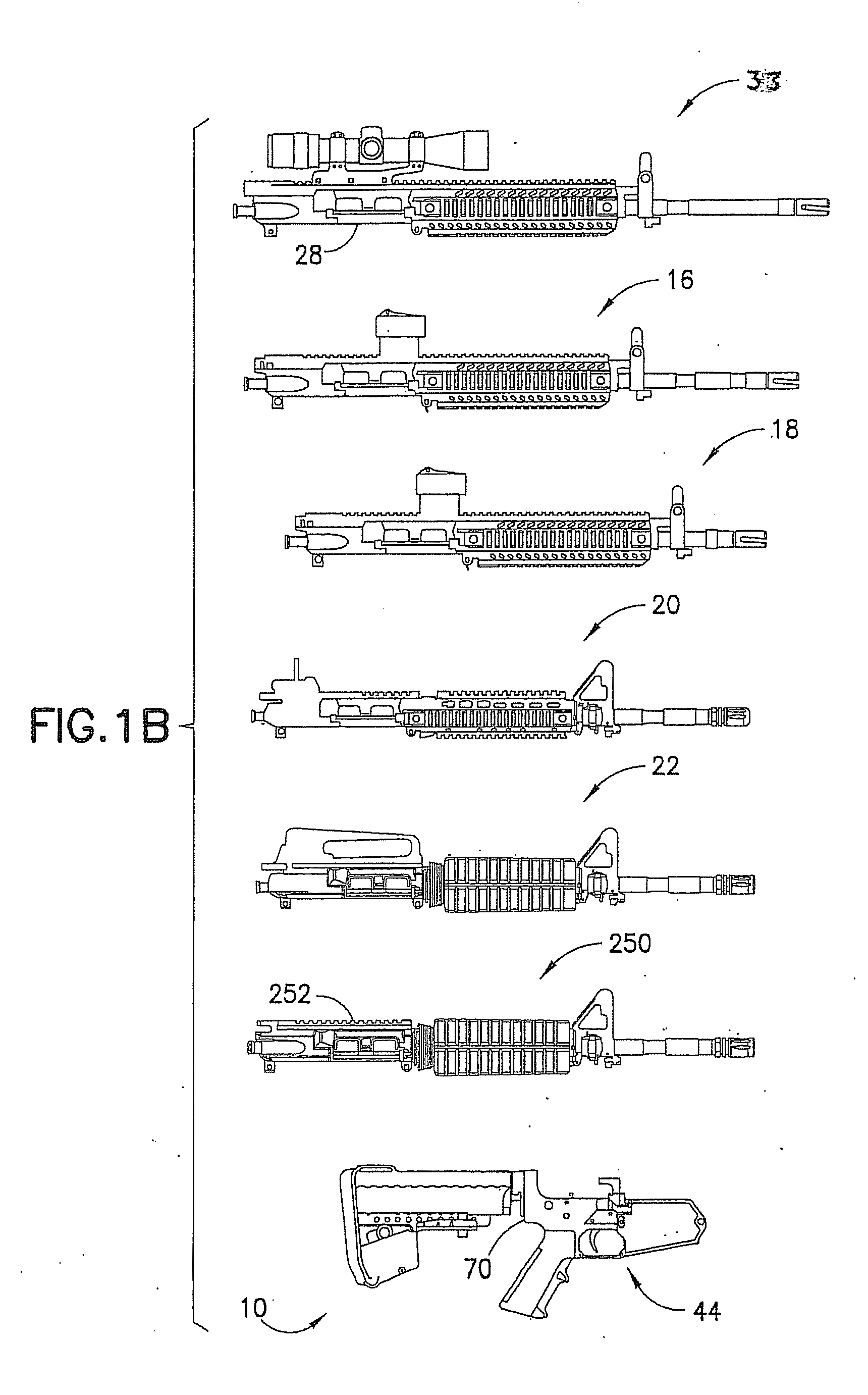
[0057]Referring now to FIG. 1A, there is shown a side view of an automatic or semi-automatic firearm 10 incorporating features in accordance with an exemplary embodiment. Referring also to FIG. 1B, there is a side view of an automatic or semi-automatic firearm 10 incorporating features in accordance with an exemplary embodiment. Firearm 10 may be a modular carbine as a user level, mission configured, light weight modular, multi caliber w...
PUM
| Property | Measurement | Unit |
|---|---|---|
| Length | aaaaa | aaaaa |
| Length | aaaaa | aaaaa |
| Diameter | aaaaa | aaaaa |
Abstract
Description
Claims
Application Information