Saddle hanger for a structure

a technology for connecting cables and hangers, which is applied in the field of connecting cables for structures, can solve the problems of increasing the cost and difficulty of manufacturing and installation, and the resistance of clips or hangers to pull ou

Active Publication Date: 2012-11-29
MITEK HLDG INC
View PDF30 Cites 34 Cited by
  • Summary
  • Abstract
  • Description
  • Claims
  • Application Information

AI Technical Summary

Benefits of technology

[0003]In one aspect of the present invention, a saddle hanger for connecting at least one bracing member to a truss chord generally comprises a base having a first end portion sized and shaped for receiving an end of a bracing member thereon. An adjacent portion is sized and shaped for receiving the truss chord thereon. The base has opposite side edges extending from the first end portion to the adjacent portion. The first end portion has a transverse edge remote from the adjacent portion and extending between the side edges. The first end portion also has a projecting element with a width less than a distance between the opposite side edges at the first end portion. The projecting element projects outward from the remainder of the transverse edge of the first end portion. A plurality of flanges extends upward from the side edges of the base. At least some of the flanges define with the base a channel for receiving one of the truss chord and bracing member.

Problems solved by technology

However, when the bracing members are loaded in tension, the clips or hangers offer low resistance to “pullout”; i.e., the bracing member pulls out of the clip connecting it to the bottom chord of the truss.
Using additional components, such as a tension tie, is not preferable, as it increases the cost and difficulty of manufacturing and installation.

Method used


Image

  • Saddle hanger for a structure
  • Saddle hanger for a structure
  • Saddle hanger for a structure

Examples


Embodiment Construction

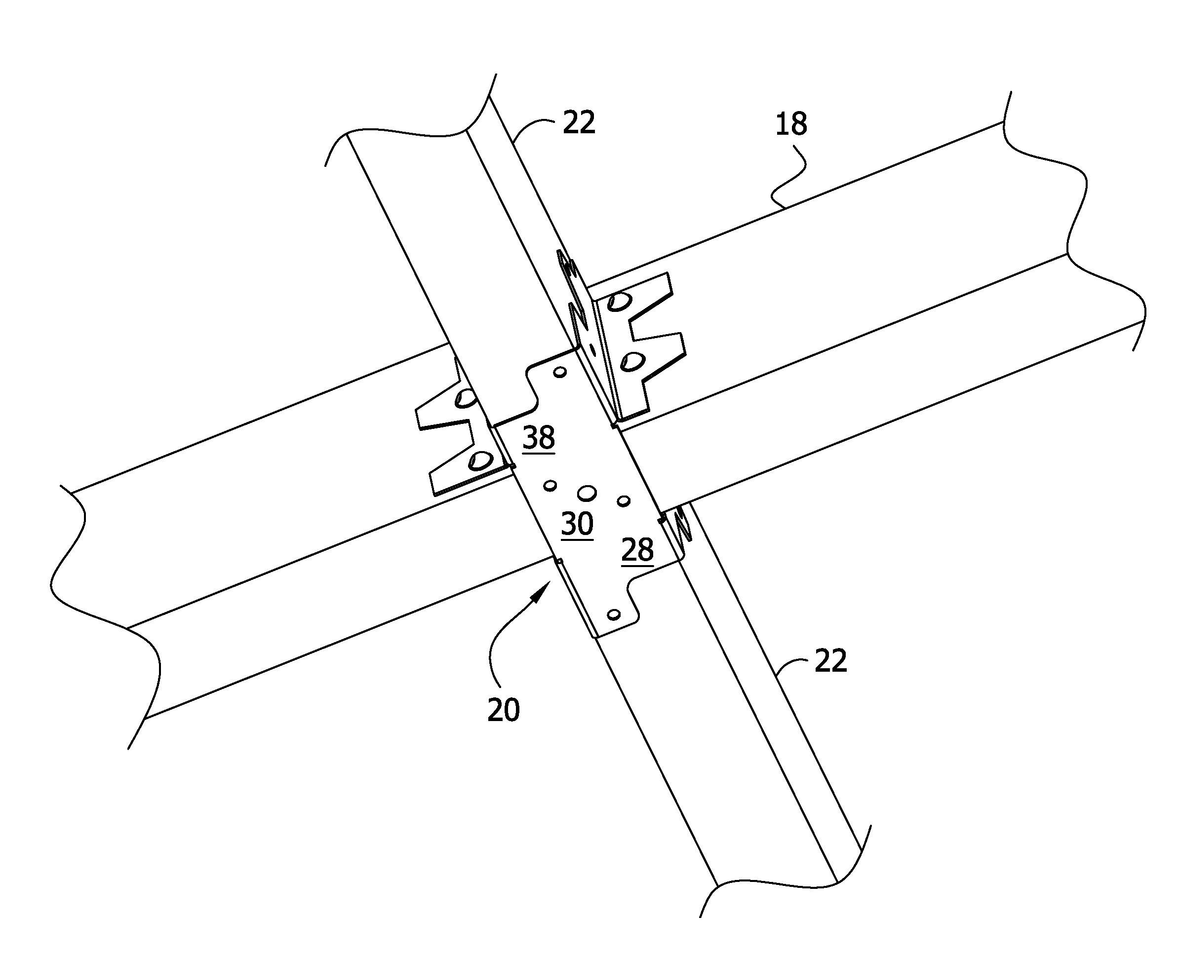
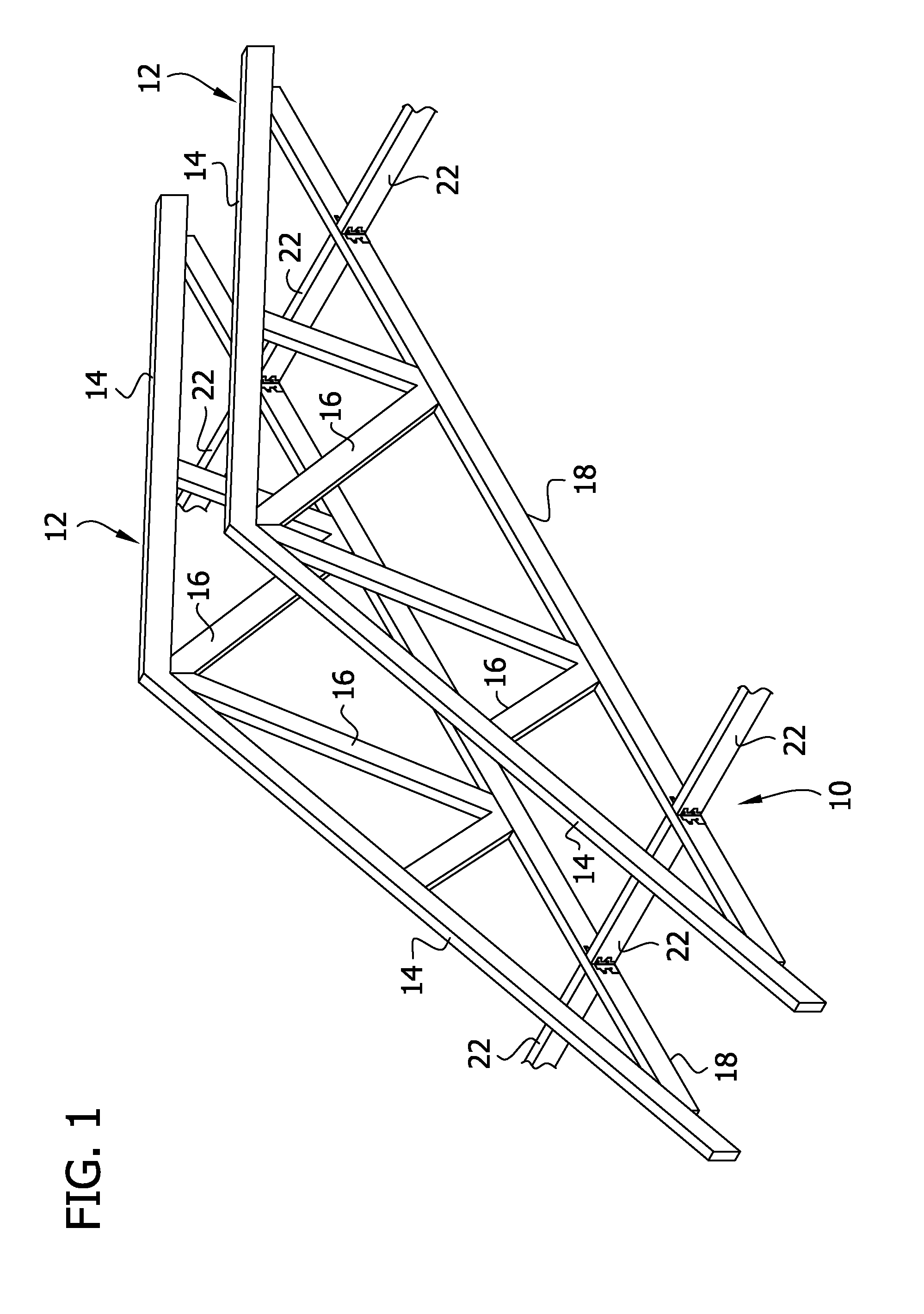
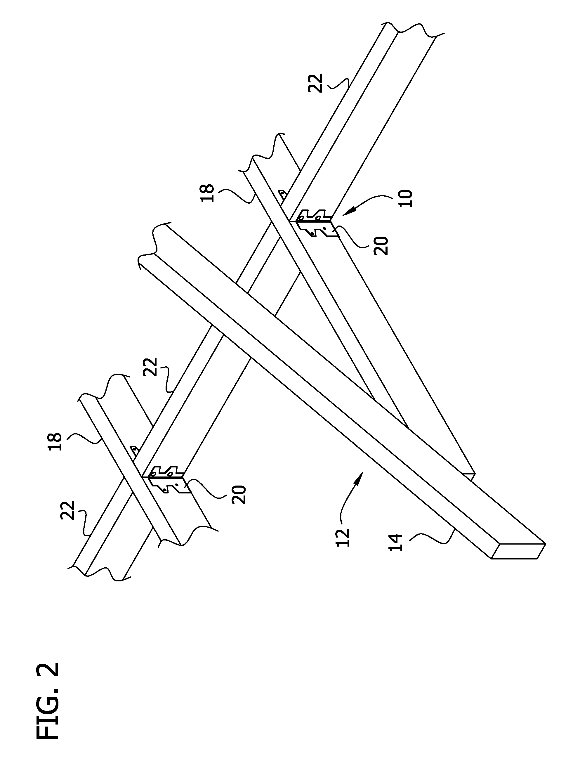
[0015]Referring to FIGS. 1-3, a connection system for structures is shown generally at 10. Roof trusses generally indicated at 12 each include truss members (broadly, “wooden structural members”) including upper chords 14, web members 16, and a bottom chord 18 joining the lower ends of the upper chords. The number and orientations of the web members 16 and chords 14, 18 may vary from the illustrated embodiment without departing from the scope of the invention, as a saddle hanger 20 according to the present invention is readily applicable to other truss configurations. Moreover, the saddle hanger 20 may be used in a structural support other than a roof truss.

[0016]For the purposes of this description, each piece of lumber incorporated as a truss member is of a rectangular cross section having two narrow sides and two wide sides. The lumber surfaces incorporating the two wide sides of the truss members will be called faces.

[0017]As seen in FIG. 1, two adjacent roof trusses 12 are conn...


PUM

PropertyMeasurementUnit
widthaaaaaaaaaa
fastening structureaaaaaaaaaa
shapeaaaaaaaaaa

Abstract

A saddle hanger for connecting at least one bracing member to a truss chord includes a base having a first end portion for receiving a bracing member and an adjacent portion for receiving a truss chord. A projecting element extends from a transverse edge of the base portion, and has a width narrower than the transverse dimension of the hanger base. A plurality of flanges extends upward from side edges of the base and defines with the base a channel for receiving one of the truss chord and bracing member. The saddle hanger can be formed from a stamped metal blank, with portions of the saddle hanger being nested in side-by-side relation to minimize the amount of material used.

Description

FIELD OF THE INVENTION[0001]The present invention generally relates to connections for structures, and more specifically, a saddle hanger for connecting a truss chord and a bracing member.BACKGROUND OF THE INVENTION[0002]The use of trusses in the building of structures is commonplace. The bottom chords of trusses are often reinforced by bracing members, specifically by lateral bracing between adjacent trusses to transfer loads. The bottom chord of the truss and the bracing member are connected by connectors such as face mount clips or hangers. However, when the bracing members are loaded in tension, the clips or hangers offer low resistance to “pullout”; i.e., the bracing member pulls out of the clip connecting it to the bottom chord of the truss. As a solution to the weak tension resistance, a face mount clip can be combined with an additional tension tie to improve performance under tension. Using additional components, such as a tension tie, is not preferable, as it increases the...

Claims


Application Information

Patent Timeline
Patent Type & Authority Applications(United States)
IPC IPC(8): E04B1/38B21D28/06
CPCE04B1/2604Y10T428/12236E04B1/2612E04B1/2608F16B9/052F16B9/058F16B2200/503
Inventor POPE, PAULGREVIOUS, TODD
Owner MITEK HLDG INC
Why Eureka
Try Eureka