Check patentability & draft patents in minutes with Patsnap Eureka AI!

Surgical tool holder

a tool holder and surgical technology, applied in the field of surgical tool holders, can solve the problems of non-patient-fixed tool holders, affecting the operation efficiency of surgical instruments, and requiring patient movement during surgery, and causing significant sensitivity to liquids or debris

Inactive Publication Date: 2012-11-29
MANOLIDIS SPIROS
View PDF17 Cites 57 Cited by
  • Summary
  • Abstract
  • Description
  • Claims
  • Application Information

AI Technical Summary

Benefits of technology

The invention allows for separate fixed parts that can connect with each other independently. This provides greater flexibility and customization options when designing products or systems.

Problems solved by technology

The technical problem addressed in this patent text is the need for a better surgical tool holding device that offers higher rigidity, easier setup, and minimal invasiveness to the patient. Current methods involve either fixed or non-fixed devices, but they all come with limitations including potential movement of the surgical team or slow recovery times after surgery. This new device would improve stability and accuracy while also providing flexibility and speed of use.

Method used


Image

  • Surgical tool holder
  • Surgical tool holder
  • Surgical tool holder

Examples


Embodiment Construction

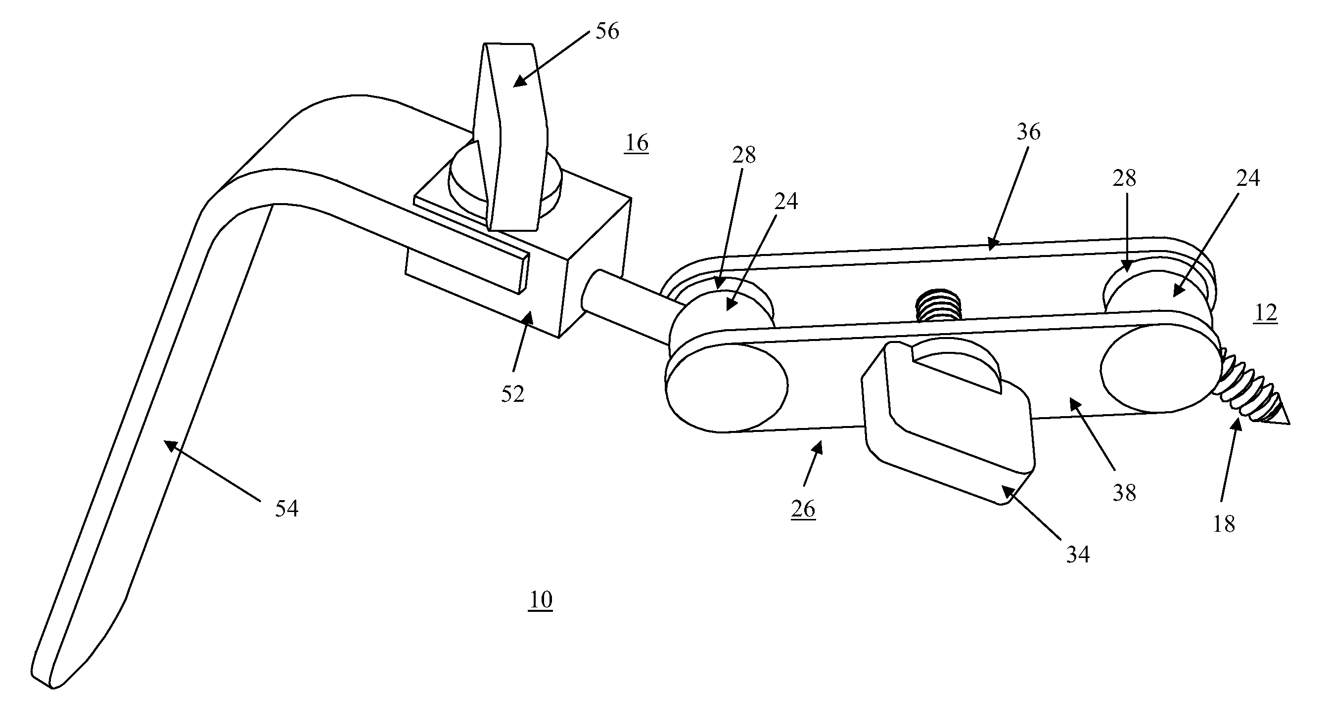
[0040]Devices and apparatuses for holding surgical tools during surgery are described herein, with reference to examples and exemplary embodiments. Specific terminology is employed in describing examples and exemplary embodiments. However, the disclosure of this patent specification is not intended to be limited to the specific terminology so selected and it is to be understood that each specific element includes all technical equivalents that operate in a similar manner.

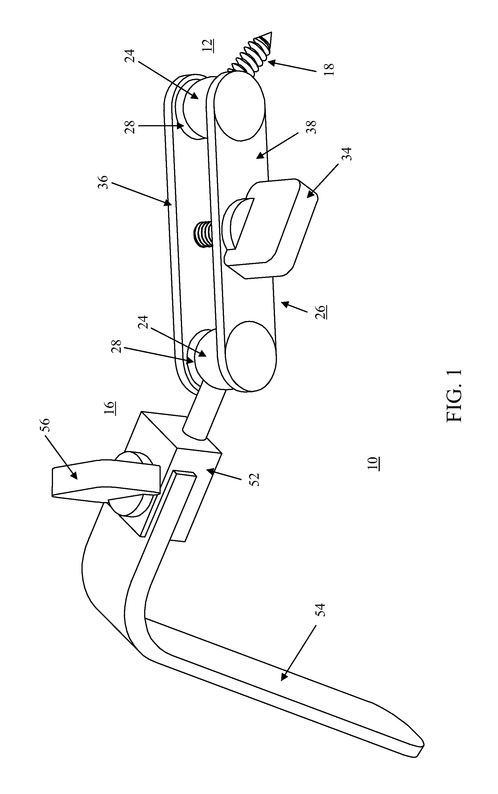
[0041]A surgical tool holder 10 is generally comprised of a base member 12, one or more intermediary members, and a tool engaging member 16. One example of a surgical tool holder 10 is shown in FIG. 1. According to the present invention, the base member 12 is attached to the patient's body so as to remain fixed during surgery. For example, the base member 12 may be screwed into the skull 11 of a patient undergoing neurosurgery, as shown in FIG. 2, and a brain retractor 54 at the distal end of surgical tool holder 10...


PUM


Abstract

Apparatuses are provided to hold surgical tools during surgery. Such apparatuses may be fixed to a patient's body and include a base member, tool engagement member and one or more intermediary members. Each member may be attached to another by a knob and mating engagement section. Fixation between members may be provided individually for each attachment or may be provided so as to fix more than one attachment at a time.

Description


Claims


Application Information

Patent Timeline
Owner MANOLIDIS SPIROS
Features
  • R&D
  • Intellectual Property
  • Life Sciences
  • Materials
  • Tech Scout
  • Unparalleled Data Quality
  • Higher Quality Content
  • 60% Fewer Hallucinations
Learn More