
Fastener identification marking

Inactive Publication Date: 2012-11-29
ILLINOIS TOOL WORKS INC
View PDF11 Cites 10 Cited by
  • Summary
  • Abstract
  • Description
  • Claims
  • Application Information

AI Technical Summary

Problems solved by technology

Being that a power driven fastener is intended to be a permanent fastening, the embedded fastener may need to be removed, possibly causing damage to the first object, the second object, or the fastener itself, in order to verify the actual length or the embedment depth of the fastener.

Method used


Image

  • Fastener identification marking
  • Fastener identification marking
  • Fastener identification marking

Examples


Embodiment Construction

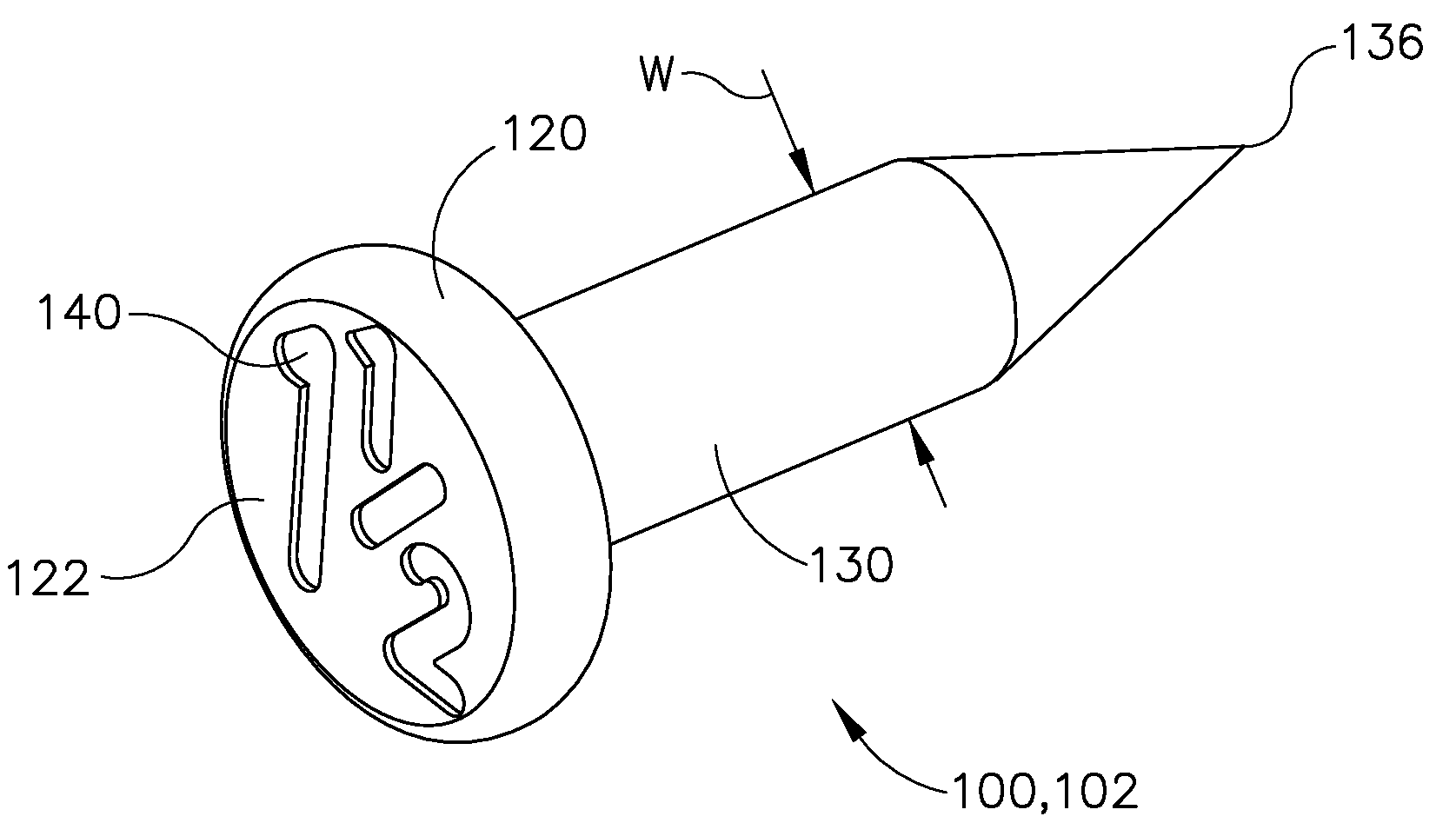
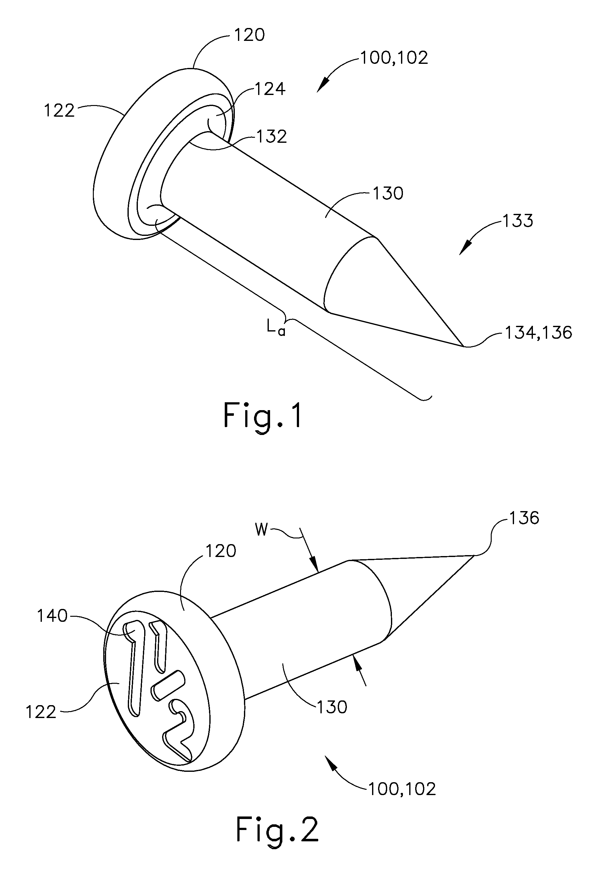
[0012]Methods and devices consistent with the present invention overcome the disadvantages of conventional fasteners by using a fastener which has an identification marking on an outer surface of the fastener's head. The identification marking preferably indicates a physical property of the fastener. By viewing the identification marking on the outer surface of the fastener's head, which is visible even after installation of the fastener, interested parties may now determine the actual length or the embedment depth of a power driven fastener after installation without having to remove the fastener, and possibly causing damage to the first object, the second object, or the fastener itself.

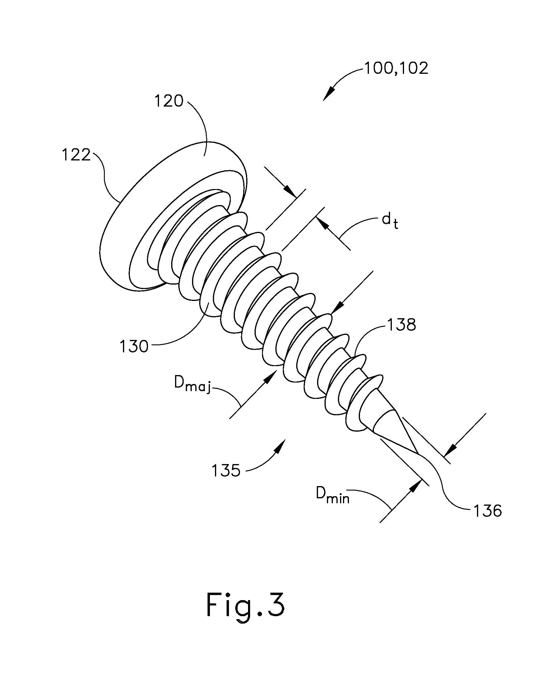
[0013]With reference to FIGS. 1, 2 and 4, there is shown one embodiment of a fastener 100 having an identification marking 140 formed on a head 120 of the fastener 100. Fastener 100 is any device which can be inserted into or through a first object 110 and then inserted into or through a second obje...


PUM


Abstract

A fastener for being inserted a first depth d1 through a first object and a second depth d2 into or through a second object, is provided. The fastener includes, but is not limited to, a head having an outer surface opposed to an inner surface, a shank connected with the inner surface of the head at a first end and forming a tip at a second end opposed to the first end, and an identification marking formed on the outer surface. The outer surface remains exposed upon the fastener being inserted into an object. The shank has an actual length La from the first end to the second end, and wherein the actual length La is equal to or greater than the sum of the first depth d1 and the second depth d2. The identification marking indicates an embedment depth de of the fastener.

Description

BACKGROUND OF THE INVENTION[0001]Certain applications require use of a power driven fastener to attach a first object, such as a metal bracket, to a second object, such as a concrete wall. After a fastener is embedded through the first object and into or through the second object, by an installer, an interested third party such as a contractor or a building inspector, does not know the actual length or the embedment depth of the fastener into the second object. Being that a power driven fastener is intended to be a permanent fastening, the embedded fastener may need to be removed, possibly causing damage to the first object, the second object, or the fastener itself, in order to verify the actual length or the embedment depth of the fastener.[0002]It would therefore be desirable to allow interested parties to determine the actual length or the embedment depth of a power driven fastener after installation without having to remove the fastener, and possibly causing damage to the first...

Claims


Application Information

Patent Timeline
IPC IPC(8): F16B15/00F16B35/00
CPCF16B1/0071F16B35/00F16B19/00F16B15/00F16B2200/95
Inventor JABLONSKI, DAVID W.ROXBURGH, JOHN JASONHEFLIN, WILLIAM M.
Owner ILLINOIS TOOL WORKS INC
Learn More