Electromagnetic relay and method of manufacturing the same

a technology of electromagnetic relay and manufacturing method, which is applied in the direction of magnets, contact mechanisms, magnetic bodies, etc., can solve the problems of shortening the operating life of electromagnetic relay, affecting the operation efficiency of electromagnetic relay, and damage to contacts and parts in the vicinity of contacts

Inactive Publication Date: 2012-12-13
FUJITSU COMPONENENT LTD
View PDF12 Cites 36 Cited by
  • Summary
  • Abstract
  • Description
  • Claims
  • Application Information

AI Technical Summary

Problems solved by technology

If the above electromagnetic relay is used to control high voltage or direct current, arcs may be generated between contacts of the electromagnetic relay to thereby shorten its operating life of the electromagnetic relay.
Although arcs may be quickly broken by methods described in Patent Documents 1 to 3, the arcs in the contacts may not be prevented from being generated, so that the arcs are still generated for a short time.
Therefore, there is a case where the contacts and parts in the vicinity of the contacts are damaged by the arcs.
Then, the operating life of the electromagnetic relay is shortened to thereby degrade safety and reliability of the electromagnetic relay.
In this case, if a component of the generated organic gas adheres to a contact or the like, an electric conduction failure may be generated in the contacts of the like.
Then, there are problems that the temperature of the permanent magnet is increased to weaken the magnetic power of the permanent magnet.

Method used


Image

  • Electromagnetic relay and method of manufacturing the same
  • Electromagnetic relay and method of manufacturing the same
  • Electromagnetic relay and method of manufacturing the same

Examples


Embodiment Construction

[0030]A description is given below, with reference to the FIG. 1 through FIG. 13 of embodiments of the present invention. The same reference symbols are attached to the same parts or the like and description of the parts is omitted.

(Electromagnetic Relay)

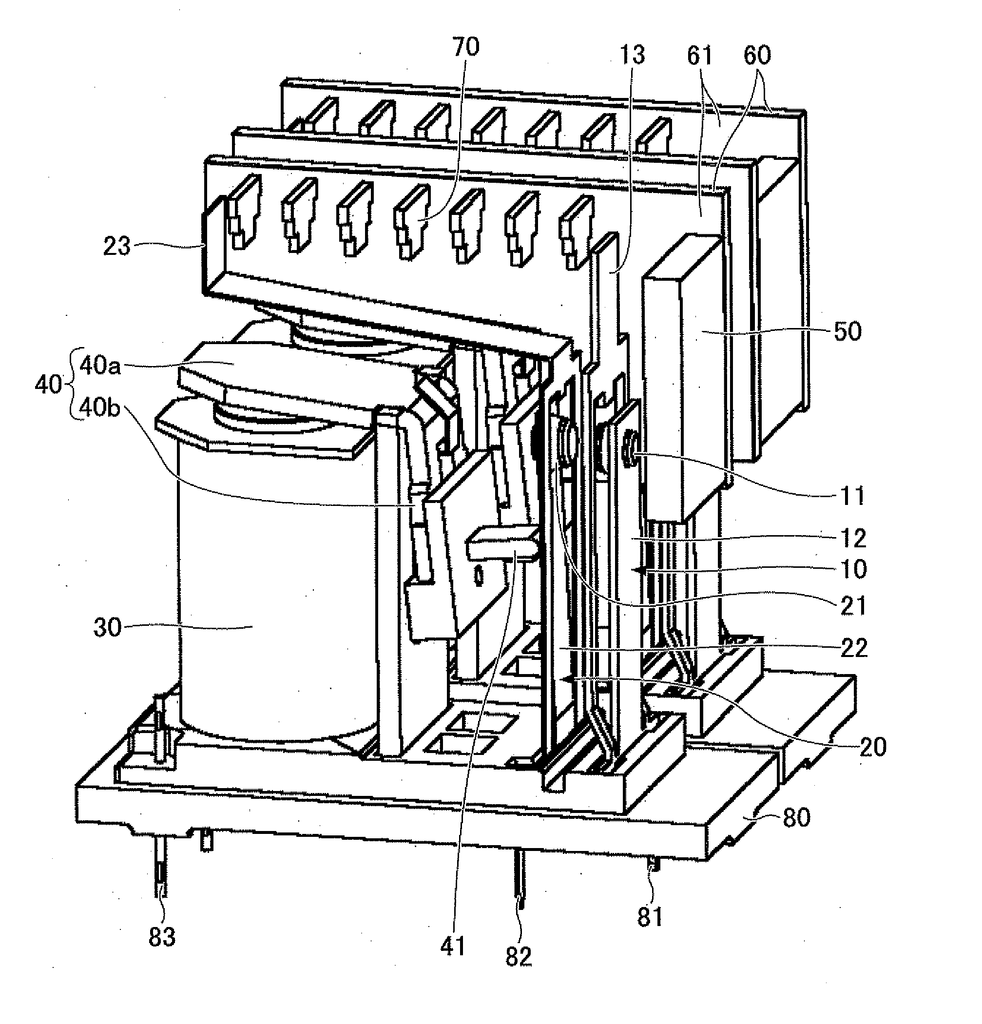
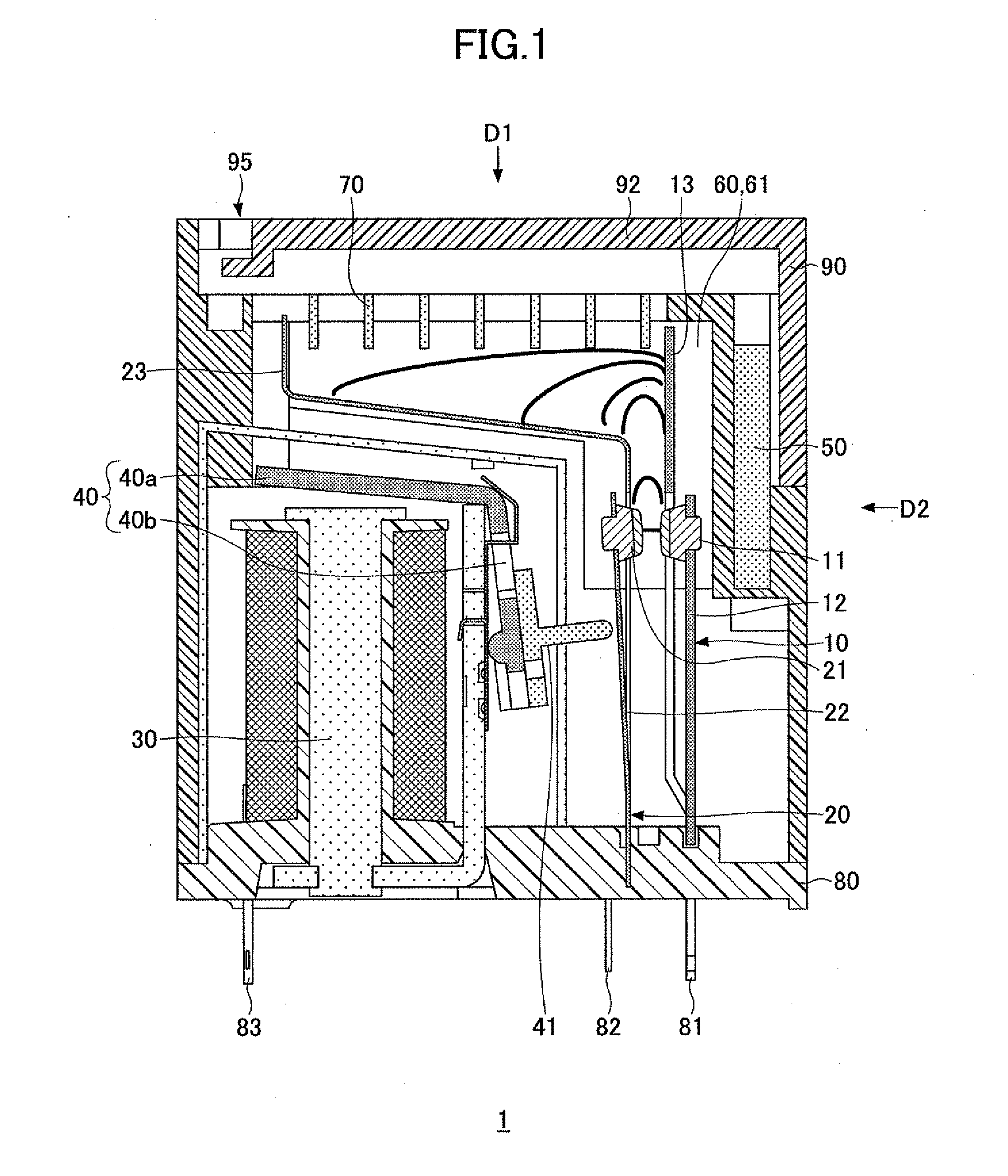
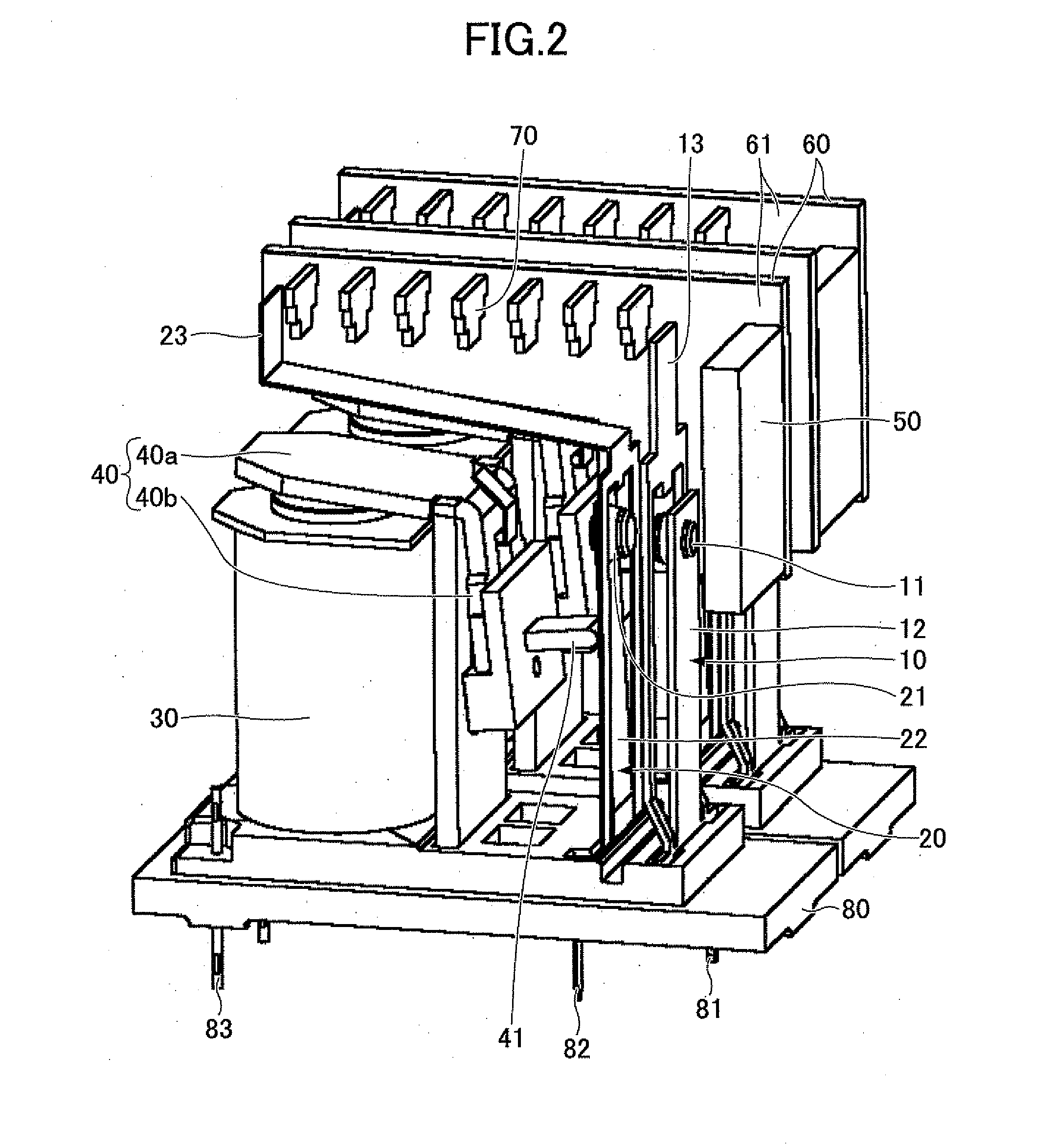
[0031]The electromagnetic relay 1 of the embodiments of the present invention is described. The electromagnetic relay 1 includes a fixed contact 11, a fixed contact spring 12, a fixed contact unit 10 having a fixed side arc runner 13, a movable contact 21, a movable contact spring 22, and a movable contact unit 20 having a movable side arc runner 23. On a side where the movable contact unit 20 is provided, an electric magnet unit 30 is provided. An arming unit 40 is provided on an end of the electric magnet unit 30. The arming unit 40 is bent to be like a letter of “V”. The arming unit 40 is connected to the electromagnetic relay 1 so as to be movable around an axis at the center of the arming unit 40. The arming unit 40 has a first...


PUM

PropertyMeasurementUnit
angleaaaaaaaaaa
forceaaaaaaaaaa
magnetic fieldaaaaaaaaaa

Abstract

A disclosed electromagnetic relay includes a fixed contact, a movable contact provided in a movable contact spring, an electric magnet causing the movable contact to contact the fixed contact by applying force via an arming unit, a magnet generating a magnetic field between the fixed contact and the movable contact, and yokes made of a magnetic material, wherein the yokes are arranged in parallel to interpose the fixed contact and the movable contact between the yokes and to apply the magnetic field generated by the magnet to an area where the fixed contact and the movable contact exist, and insulating portions are provided on inner surfaces of the yokes facing the fixed contact and the movable contact, respectively.

Description

CROSS-REFERENCE TO RELATED APPLICATIONS[0001]This patent application is based upon and claims the benefit of priority of Japanese Patent Application No. 2011-127740 filed on Jun. 7, 2011, Japanese Patent Application No. 2011-127741 filed on Jun. 7, 2011, and Japanese Patent Application No. 2011-127742 filed on Jun. 7, 2011, the entire contents of which are incorporated herein by reference.BACKGROUND OF THE INVENTION[0002]1. Field of the Invention[0003]The present invention generally relates to an electromagnetic relay and a method of manufacturing the electromagnetic relay.[0004]2. Description of the Related Art[0005]An electromagnetic relay such as a relay is an electronic component which controls electric power to be turned on or off by using an electric magnet. If the above electromagnetic relay is used to control high voltage or direct current, arcs may be generated between contacts of the electromagnetic relay to thereby shorten its operating life of the electromagnetic relay.[...

Claims


Application Information

Patent Timeline
Patent Type & Authority Applications(United States)
IPC IPC(8): H01H51/00H01F7/06
CPCH01H9/34H01H9/443H01H9/46H01H50/047Y10T29/4902H01H50/38H01H50/56H01H51/06H01H50/28H01H50/54
Inventor IWAMOTO, DAIEIYUBA, TAKASHI
Owner FUJITSU COMPONENENT LTD
Why Eureka
Try Eureka