Quick-release device

Active Publication Date: 2012-12-20
CHANG CHIN CHAO
View PDF6 Cites 21 Cited by
  • Summary
  • Abstract
  • Description
  • Claims
  • Application Information

AI Technical Summary

Benefits of technology

[0012]The main objective of the present invention is to provide an improved quick-release device that inclu

Problems solved by technology

However, the fork (4) usually has two parallel tubes such that the load for the conventional quick-release device to th

Method used


Image

  • Quick-release device
  • Quick-release device
  • Quick-release device

Examples


Embodiment Construction

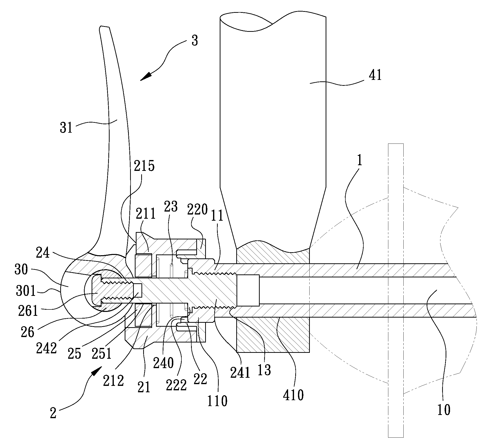
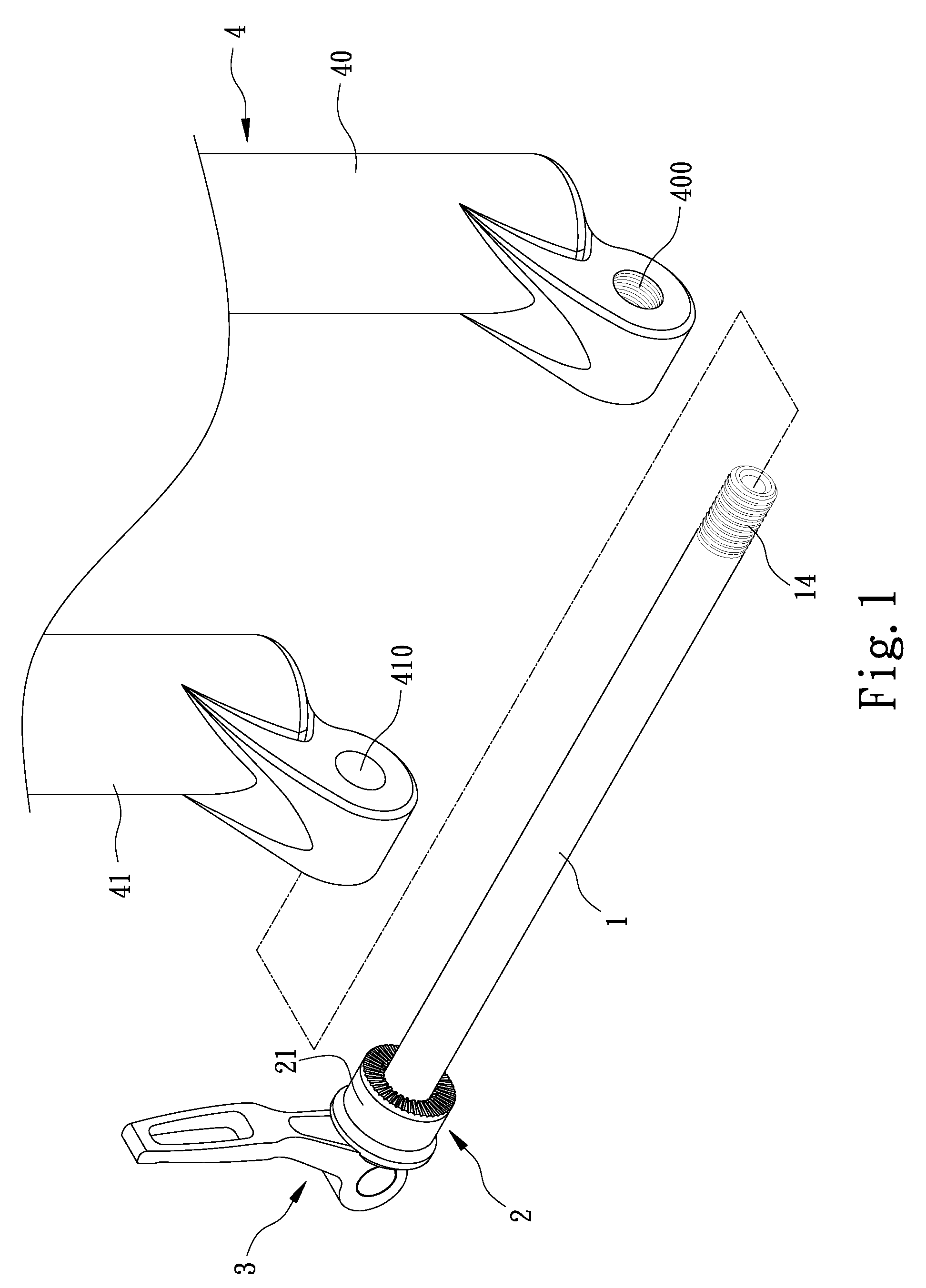
[0023]Referring to the drawings and initially to FIGS. 1-4, a quick-release device in accordance with the present invention is adapted to be mounted on a fork (4) that has a first tube (40) and a second tube (41) parallel to each other, wherein the first tube (40) has a threaded hole (400) transversely defined in a free end thereof and the second tube (41) has a through hole (410) transversely defined in a free end thereof. The threaded hole (400) and the through hole (410) align with each other.

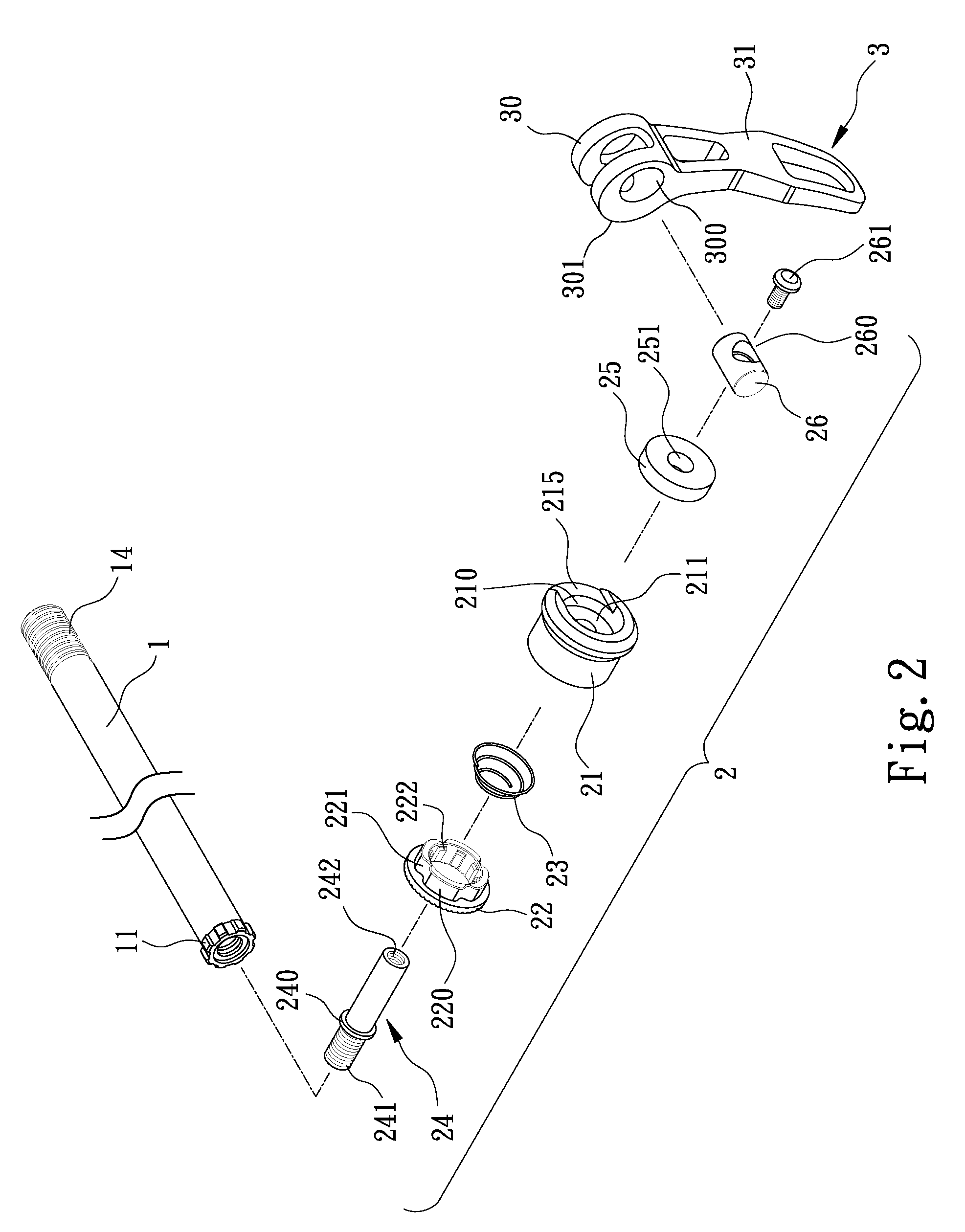
[0024]The quick-release device in accordance with the present invention comprises a shank (1), an engaging assembly (2) mounted to a first end of the shank (1) and a lever (3) pivotally connected to the engaging assembly (2).

[0025]The shank (1) includes an outer threaded portion (14) formed on a first end and a flange (11) radially extending from a second end thereof. A series of first teeth (110) is peripherally formed on the flange (11) and a through hole (10) is centrally and longitudinal...


PUM


Abstract

A quick-release device includes a shank and a flange radially extending from one end of the shank. A ring is sleeved on the shank and engaged to the flange. A sleeve is co-axially connected and engaged to the ring. A washer is received in the sleeve. A shaft is co-axially connected to the shank and sequentially extending through the ring, the sleeve and the washer. A pivot is transversely mounted to a distal end of the shaft and abutting the washer. A lever is pivotally mounted onto the pivot for selectively forcedly and inwardly pushing the washer and engaged to the sleeve.

Description

CROSS-REFERENCE TO RELATED APPLICATION[0001]This application is a continuation-in-part application of U.S. patent application Ser. No. 13 / 160,508, filed Jun. 15, 2011, and entitled “QUICK-RELEASE DEVICE”, now pending, the contents of which are included herein by reference.BACKGROUND OF THE INVENTION[0002]1. Field of the Invention[0003]The present invention relates to a quick-release device, and more particularly to a quick-release device that includes a lever selectively driving a tubular structure thereof for detaching the quick-release device when being released.[0004]2. Description of Related Art[0005]A conventional quick-release device in accordance with the prior art shown in FIGS. 5 and 6 is adapted to be mounted on a fork (4), wherein the fork (4) includes a tube (41) having a through hole (410) defined in a free end thereof to allow the quick-release device extending through the tube (41).[0006]The conventional quick-release device includes a shaft (5) extends through the th...

Claims


Application Information

Patent Timeline
IPC IPC(8): F16B7/00
CPCB62K2206/00B62K25/02Y10T403/595Y10T403/32442
Inventor CHANG, CHIN-CHAO
Owner CHANG CHIN CHAO
Why Eureka
Try Eureka