AI technical title is built by PatSnap AI team. It summarizes the technical point description of the patent document.
a hyperthermia treatment and probe technology, applied in the field of hyperthermia treatment, can solve the problems of inability of surgeons to control the heating, no system available, and disclosure of patents that have not led to commercially viable hyperthermia treatment systems, so as to prevent overheating cells
Inactive Publication Date: 2013-01-03
MONTERIS MEDICAL CORP +1
View PDF0 Cites 1 Cited by
Summary
Abstract
Description
Claims
Application Information
AI Technical Summary
This helps you quickly interpret patents by identifying the three key elements:
Problems solved by technology
Method used
Benefits of technology
Benefits of technology
The patent text describes a method for controlling the temperature of a patient during surgery using MRI technology. The method involves monitoring the temperature of the patient's body and controlling the application of heat to the surgery area based on the temperature change. This helps to prevent overheating of cells outside the targeted tissue. The technical effect of this method is an improved non-invasive control system that ensures safe surgery.
Problems solved by technology
It is difficult therefore for the surgeon to effect a controlled heating which heats the entire lesion while minimizing damage to surrounding tissue.
The imaging system thus generates for the surgeon a location of the lesion to be excised but there is no system available which allows the surgeon to use the imaging system to control the heating effect.
The disclosure of the patent has not led to a commercially viable hyperthermic treatment system.
Again this patented arrangement has not led to a commercially viable hyperthermia surgical system.
This arrangement has not achieved commercial or medical success.
This arrangement however provides no feedback control of the heating effect.
U.S. Pat. No. 5,785,704 (Bille) assigned to MRC Systems GmbH issued Jul. 28, 1996 discloses a particular arrangement of laser beam and lens for use in irradiation of brain tumors but does not disclose methods of feedback control of the energy.
RI. However none of these papers describes an arrangement in which the energy is controlled by feedback from the monitoring arrangem
Method used
Image
Click on the blue label to locate the original text in one second.
Reading with bidirectional positioning of images and text.
Examples
Embodiment Construction
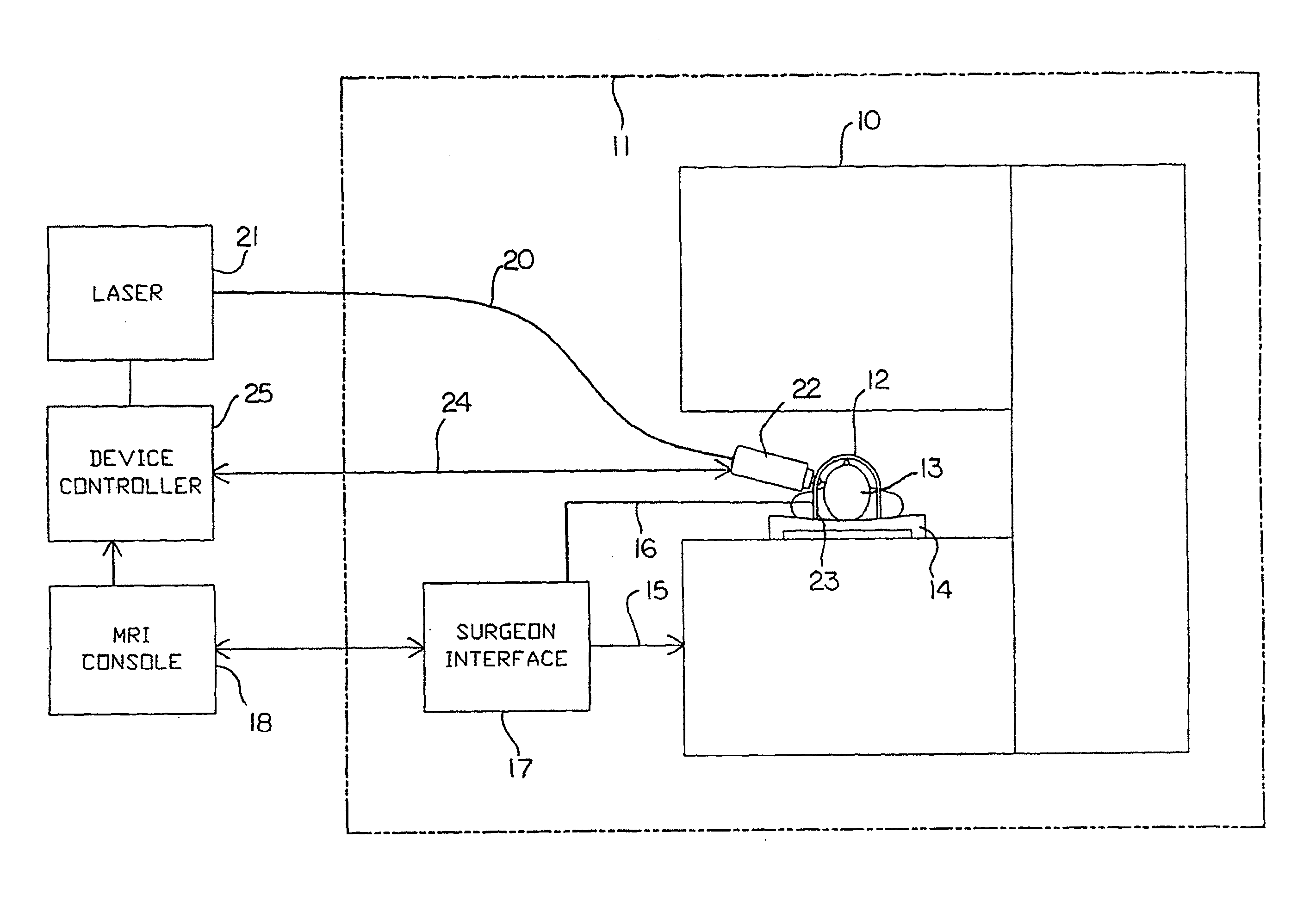
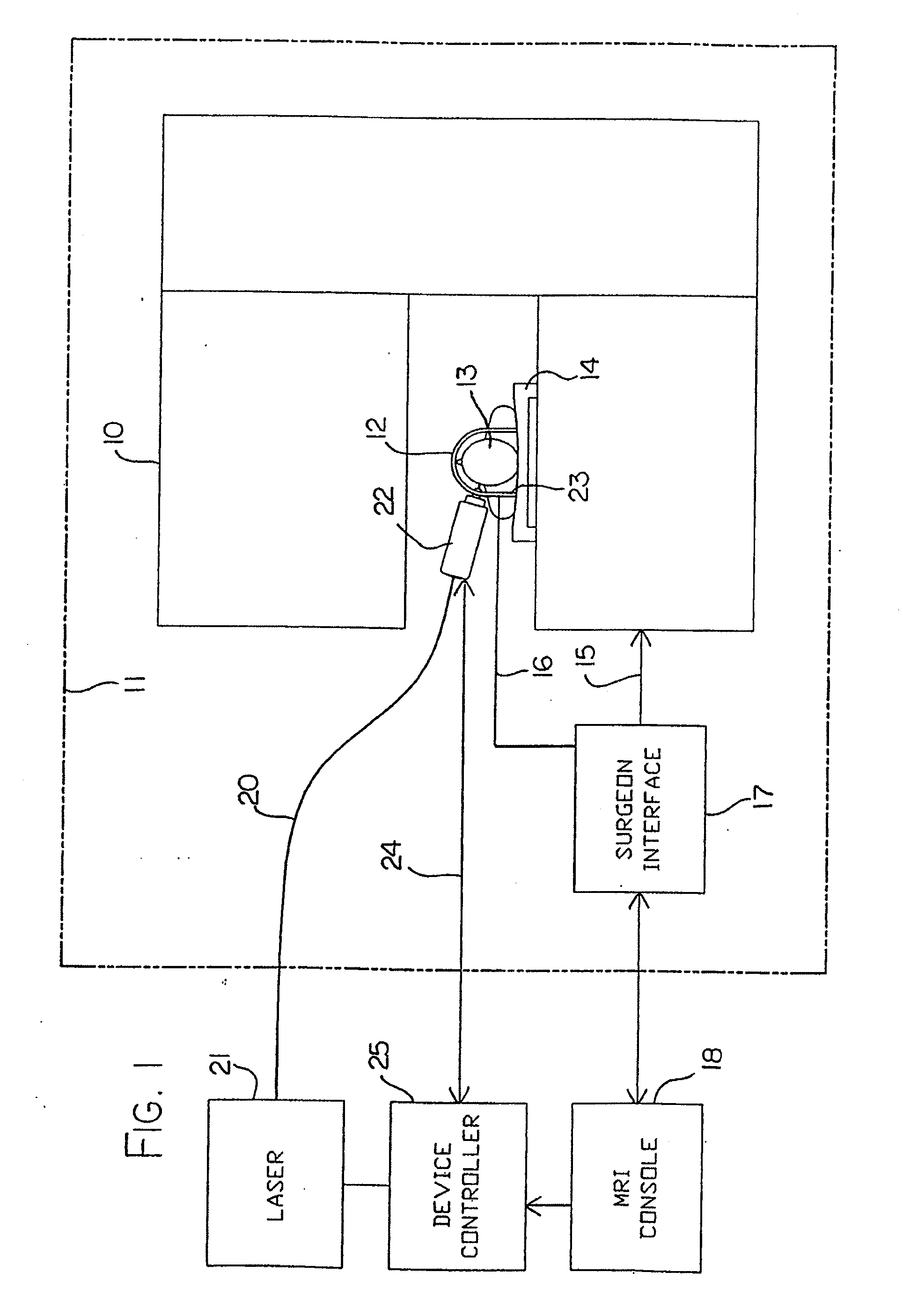
[0123]In FIG. 1 is shown schematically an apparatus for carrying out MRI controlled laser treatment. The apparatus comprises a magnetic resonance imaging system including a magnet 10 provided within a shielded room 11. The magnet 10 can be of any suitable construction and many different magnet arrangements are available from different manufacturers. The magnet includes field coils for generating variations in the magnetic field which are not shown since these are well known to one skilled in the art together with a radio frequency antenna coil which receives signals from the sample in this case indicated as a human patient 13.
[0124]The patient 13 rests upon a patient support table 14 on which the patient is supported and constrained against movement for the operative procedure. The fields of the magnet are controlled on an input control line 15 and the output from the antenna coil is provided on an output line 16 both of which communicate through a surgeon interface 17 to the conven...
PUM
Abstract
A probe that emits energy to coagulate lesions is disclosed. The probe is constructed and arranged to emit light from its distal end, either at an angle to its longitudinal axis, or along its longitudinal axis. Optionally, an end reflector may be used to direct the energy in a beam to one side of the fiber end. An MRI system is arranged to generate a series of output signals indicative of temperature in the targeted area. The application of energy is stopped when the temperature at the boundary of the lesion reaches the required hyperthermic temperature. Cooling of the tip portion of the probe is effected by expansion of a supplied cooling fluid through a restrictive orifice into an expansion zone at the probe end to minimize collateral tissue damage.
Description
CROSS REFERENCE TO RELATED APPLICATIONS[0001]This application is a continuation of U.S. application Ser. No. 11 / 957,876, filed on Dec. 17, 2007, which is a divisional of U.S. application Ser. No. 10 / 701,834, filed Nov. 5, 2003, now U.S. Pat. No. 7,344,529, which is a continuation-in-part of U.S. application Ser. No. 10 / 014,846, filed on Dec. 14, 2001, now U.S. Pat. No. 7,167,741 which is a continuation-in-part of International application Ser. No.: PCT / CA01 / 00905, filed on Jun. 15, 2001, which claims priority to U.S. application Ser. No. 09 / 593,699, filed on Jun. 15, 2000, now U.S. Pat. No. 6,418,337, the entireties of which are hereby incorporated by reference.BACKGROUND OF THE INVENTION[0002]The treatment of tumors by hyperthermia is known. In one known process, tumors and other lesions to be treated can be heated above a predetermined temperature of the order of 55 C so as to coagulate the portion of tissue heated. The temperature range is preferably of the order of 55 to 65 C an...
Claims
Application Information
Patent Timeline
Application Date:The date an application was filed.
Publication Date:The date a patent or application was officially published.
First Publication Date:The earliest publication date of a patent with the same application number.
Issue Date:Publication date of the patent grant document.
PCT Entry Date:The Entry date of PCT National Phase.
Estimated Expiry Date:The statutory expiry date of a patent right according to the Patent Law, and it is the longest term of protection that the patent right can achieve without the termination of the patent right due to other reasons(Term extension factor has been taken into account ).
Invalid Date:Actual expiry date is based on effective date or publication date of legal transaction data of invalid patent.
Patent Type & AuthorityApplications(United States)

