Eureka AIR delivers breakthrough ideas for toughest innovation challenges, trusted by R&D personnel around the world.

Slide assembly and connection device

Active Publication Date: 2013-01-17
KING SLIDE WORKS CO LTD +1
View PDF4 Cites 27 Cited by
  • Summary
  • Abstract
  • Description
  • Claims
  • Application Information

AI Technical Summary

Benefits of technology

The present invention is a slide assembly that includes an outer rail, a middle rail, and an inner rail. The slide assembly also includes a locking member, a releasing member, a synchronizing member, and a connection member. The locking member has a fixing portion, a locking portion, and a releasing portion. The releasing portion protrudes from the fixing portion and includes a guide surface that supports the releasing portion. The synchronizing member has a protrusion with an inclined surface. The connection member has an end portion and a shoulder portion that engages with the protrusion of the synchronizing member. The invention allows for secure locking of the middle rail relative to the outer rail and synchronous movement of the inner rail with the middle rail. The technical effects of the invention include improved stability and smooth operation of the slide assembly.

Problems solved by technology

Furthermore, the locking mechanism and the synchronizing mechanism are individually installed and which require more machining steps and the manufacturing cost is high.

Method used


Image

  • Slide assembly and connection device
  • Slide assembly and connection device
  • Slide assembly and connection device

Examples


Embodiment Construction

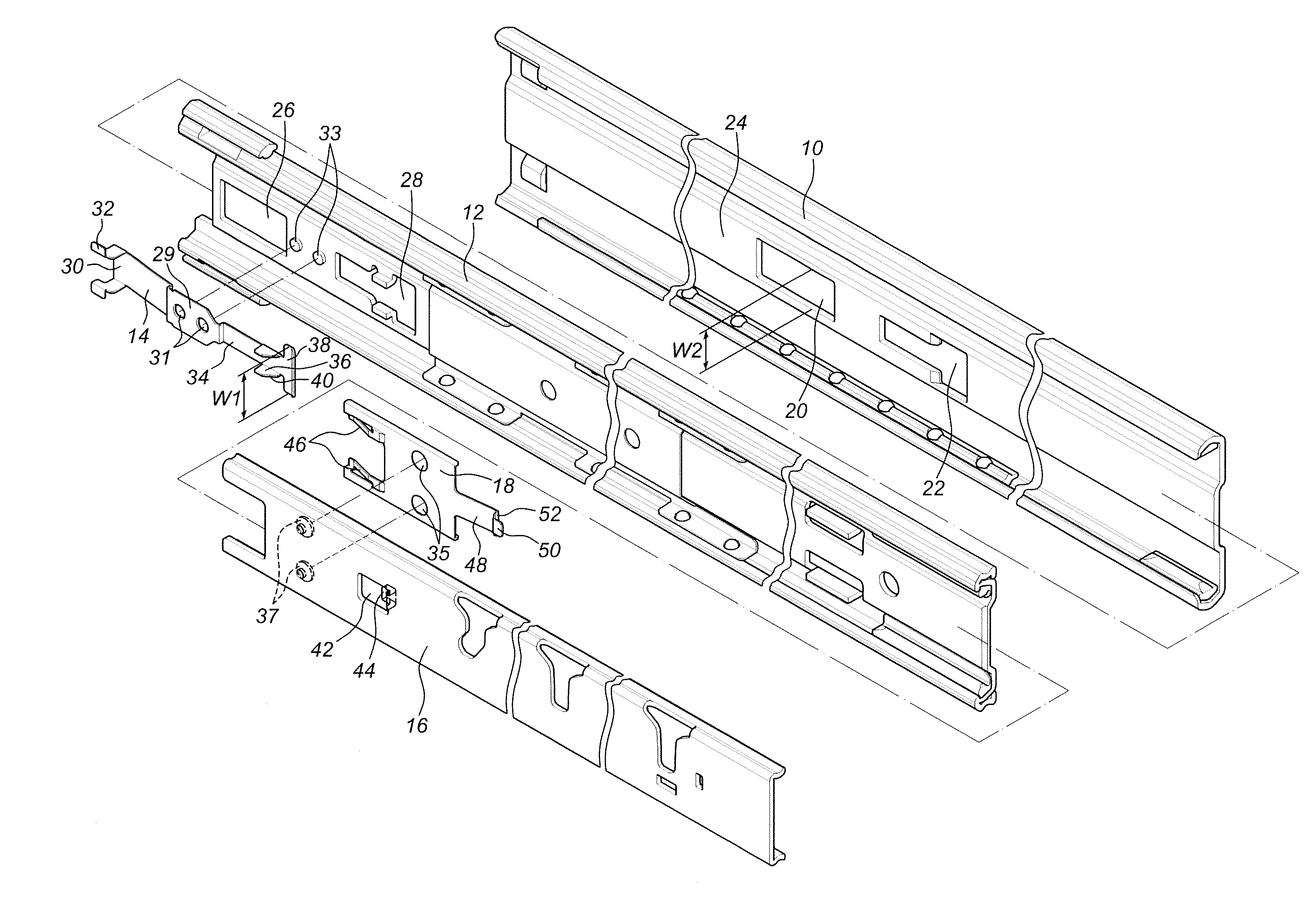
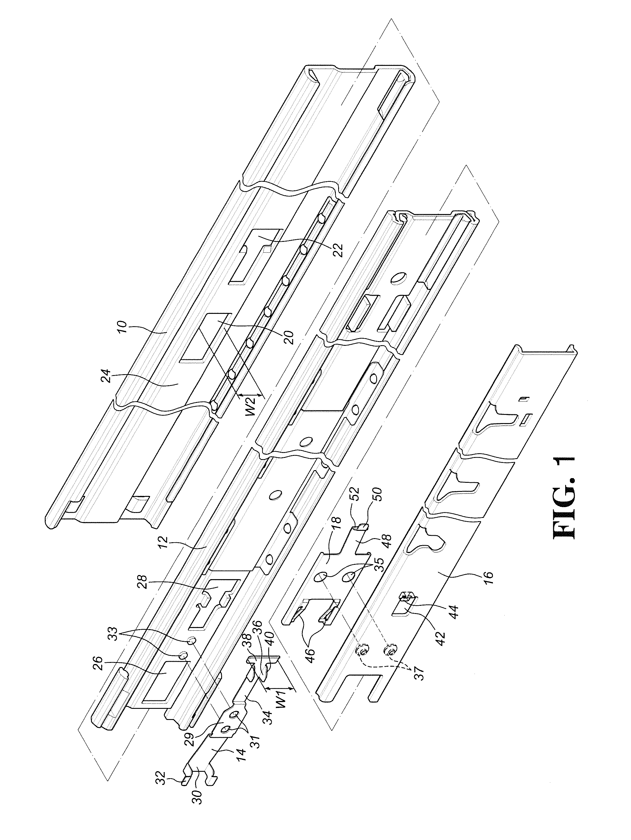
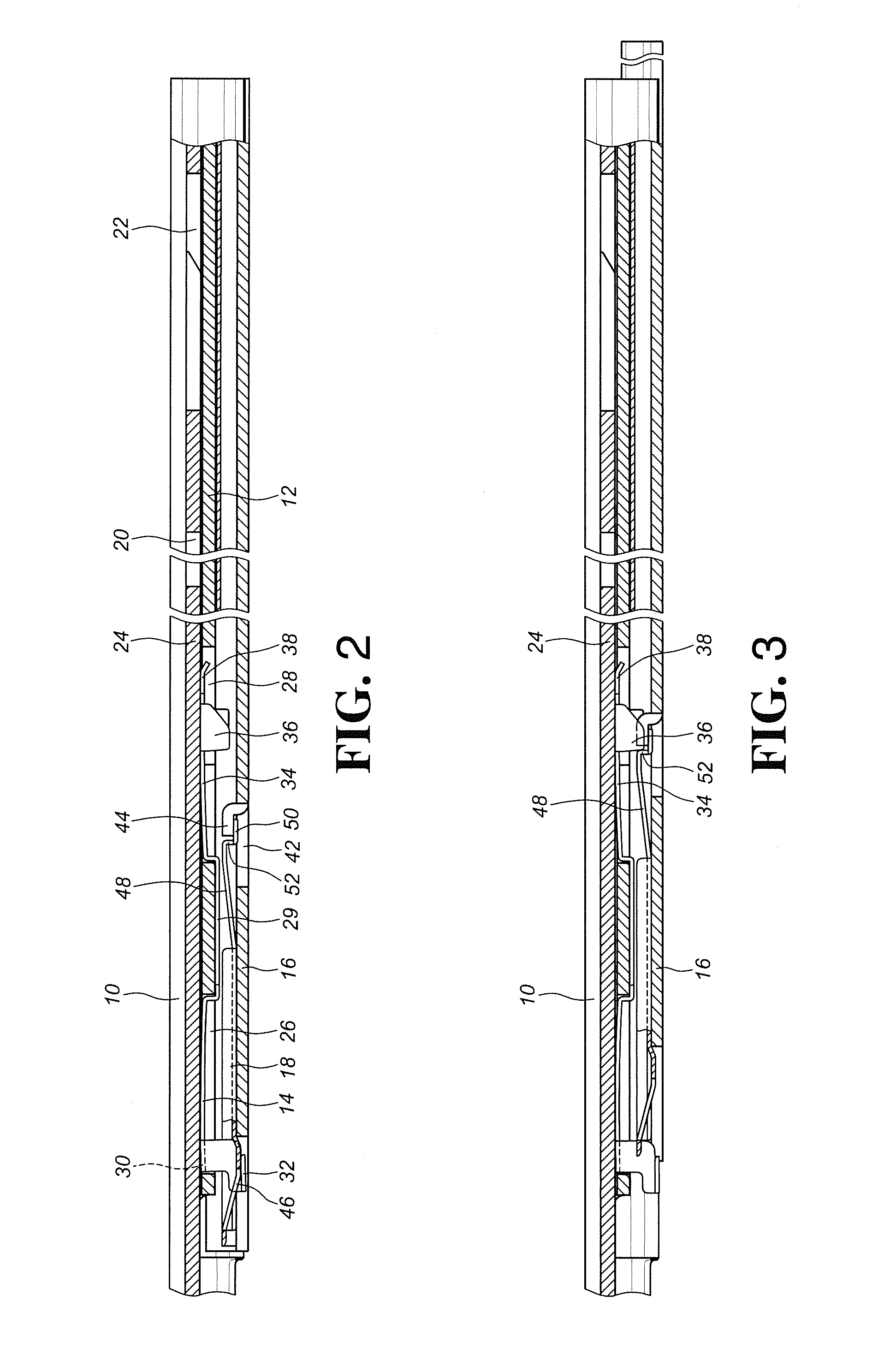
[0029]Referring to FIGS. 1 and 2, the slide assembly of the present invention comprises an outer rail 10, a middle rail 12, a locking member 14, an inner rail 16 and a releasing member 18.

[0030]The outer rail 10 comprises a locking hole 20, a releasing hole 22 and a protruding middle section 24 which faces the middle rail 12. The middle rail 12 is slidably connected to the outer rail 10 and has a first hole 26 and a second hole 28 defined therein. When the first hole 26 is located corresponding to the locking hole 20, the second hole 28 is located corresponding to the releasing hole 22 as shown in FIG. 4. A locking member 14 has a fixing portion 29 extending therefrom which is fixed to the middle rail 12.

[0031]The fixing portion 29 has two holes 31 and the middle rail 12 has two bosses 33 which are located corresponding to the holes 31. The bosses 33 are fixed to the holes 31 by a known way such as riveting to fix the locking member 14 to the middle rail 12.

[0032]The locking member ...


PUM


Abstract

A slide assembly and a connection device include an outer rail, a middle rail slidably connected to the outer rail, and an inner rail slidably connected to the middle rail. The middle rail has a locking member and a synchronizing member extends from the locking member. A releasing member is fixed to the inner rail and a connection member extends from the releasing member. The middle and inner rails are synchronously pulled from the outer rail and when the middle rail is positioned at a desired position, the inner rail is continuously pulled out by the connection between the locking member and the outer rail and by the connection member disengaged from the synchronizing member. When the inner rail is retracted relative to the middle rail, the releasing member releases the middle rail from the outer rail and the middle rail is retracted relative to the outer rail.

Description

FIELD OF THE INVENTION[0001]The present invention relates to a slide assembly and a connection device of the slide assembly, and more particularly, to a three-stage slide assembly and the connection device for positioning the middle rail and the outer rail, and the middle rail synchronously moved with the inner rail.BACKGROUND OF THE INVENTION[0002]U.S. Pat. No. 6,464,311 discloses a “Lock and release mechanism for slide assembly” and U.S. Pat. No. 7,357,468 discloses a “Locating structure for a slide assembly”.[0003]U.S. Pat. No. 6,997,529 discloses a “Synchronizing device for a tri-section slide” and U.S. Pat. No. 7,413,269 discloses a “Synchronous system for a three-stage ball bearing slide”.[0004]These locking and synchronizing mechanisms mentioned above are characterized in the engagement between the engaging block and the engaging hole or engaging recess, so that the rails are smoothly moved and synchronized, and the disengagement between the engaging block and the engaging ho...

Claims


Application Information

Patent Timeline
IPC IPC(8): F16C17/26F16C17/00
CPCA47B88/10A47B2210/0016A47B2210/0081A47B2210/0059A47B2210/007A47B2210/0032A47B88/493
Inventor CHEN, KEN-CHINGHUANG, CHIEN-LIWANG, CHUN-CHIANG
Owner KING SLIDE WORKS CO LTD
Why Eureka
Eureka Blog
Learn More