Mechanical locking system for floor panels

a technology of locking system and floor panel, which is applied in the direction of floor, building components, floors, etc., can solve the problems of separation force, complicated snap connection, and inability to adjust the width of the floor panel,

Active Publication Date: 2013-01-24
CERALOC INNOVATION AB
View PDF8 Cites 145 Cited by
  • Summary
  • Abstract
  • Description
  • Claims
  • Application Information

AI Technical Summary

Benefits of technology

[0023]An overall objective of embodiments of the present disclosure is to provide a locking system for primarily rectangular floor panels with long and short edges installed in parallel rows, which allows that the short edges may be locked to each other automatically without a snap action that creates a locking resistance and separation

Problems solved by technology

Such a snap connection is complicated since a hammer and a tapping block may need to be used to overcome the friction between the long edges and to bend the strip during the snapping action.
Such a side push action could be difficult to combine with a simple angling and the friction may be too strong for wide panels.
This c

Method used


Image

  • Mechanical locking system for floor panels
  • Mechanical locking system for floor panels
  • Mechanical locking system for floor panels

Examples


Embodiment Construction

[0059]To facilitate understanding, several locking systems in the figures are shown schematically. It should be emphasised that improved or different functions may be achieved using combinations of the preferred embodiments.

[0060]All embodiments may be used separately or in combinations. Angles, dimensions, rounded parts, spaces between surfaces etc are only examples and may be adjusted within the basic principles of the disclosure.

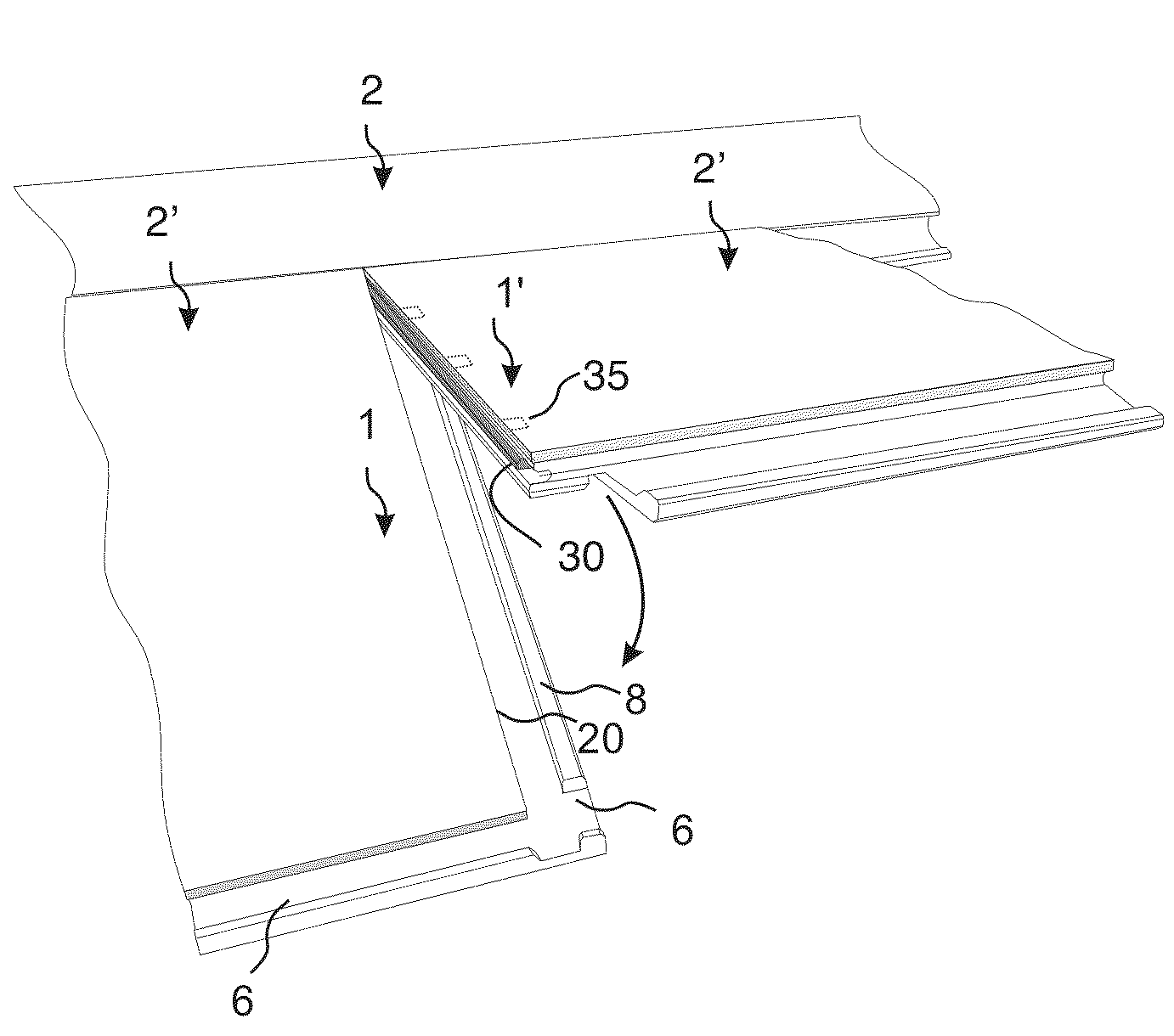
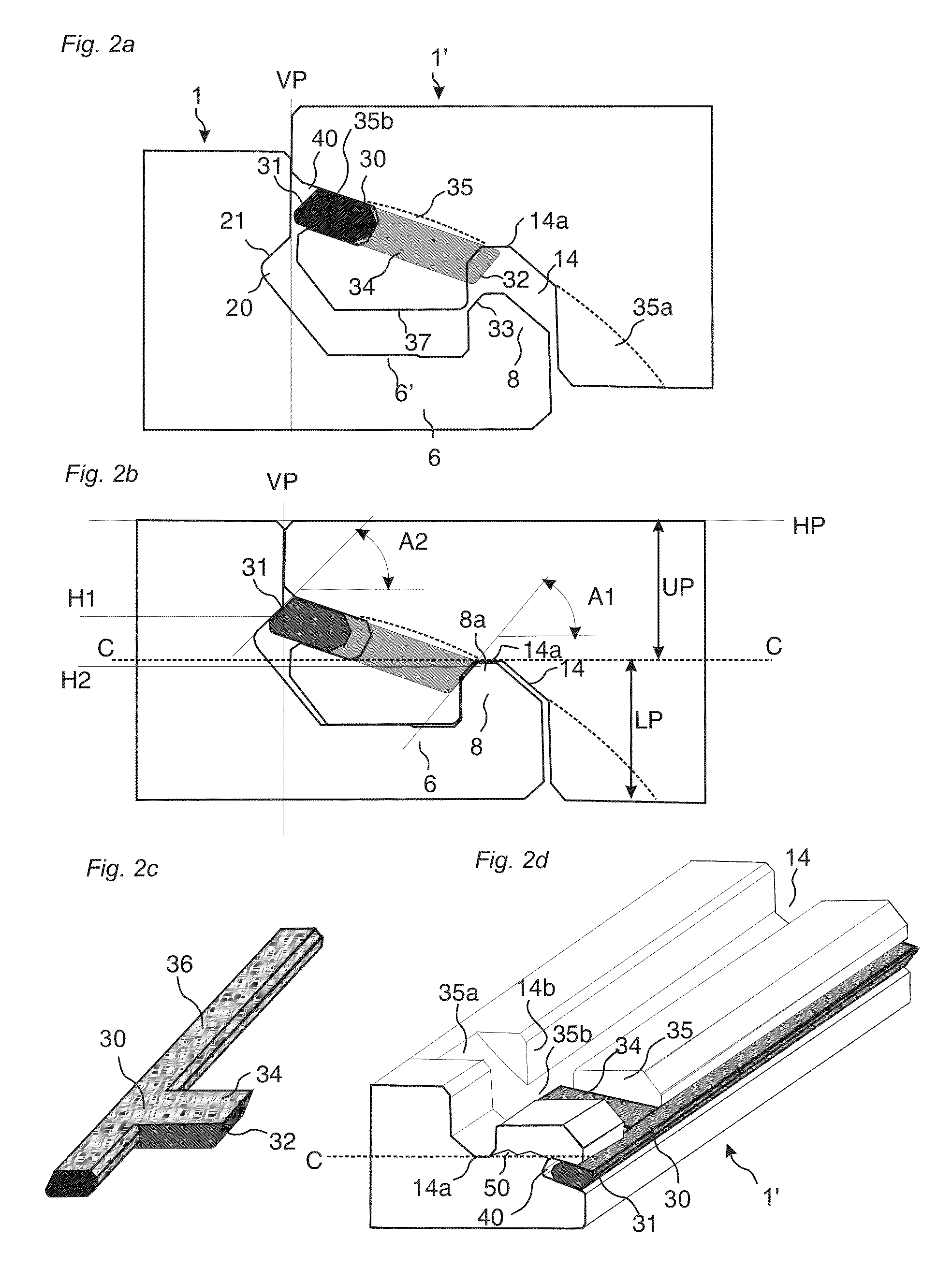
[0061]FIGS. 2a-2d show a first preferred embodiment of a short edge locking system provided with a flexible and displaceable tongue 30 in an edge of a second panel 1′ inserted in a displacement groove 40 and extending along the edge of the second panel. The displaceable tongue 30 has a tongue locking surface 31 located at an upper and outer part that cooperates with a groove locking surface 21 located at an inner and upper part of a tongue groove 20 formed in an adjacent edge of a first panel 1. The locking surfaces lock the panels in a first vertical dir...


PUM


Abstract

Floor panels are shown, which are provided with a vertical locking system on short edges having a displaceable tongue that is displaced in one direction into a tongue groove during vertical displacement of two panels.

Description

CROSS REFERENCE TO RELATED APPLICATIONS[0001]The present application claims the benefit of U.S. Ser. No. 61 / 509,309, which was filed on Jul. 19, 2011, and the entire contents of which are incorporated herein by reference.TECHNICAL FIELD[0002]The disclosure generally relates to the field of mechanical locking systems for floor panels and building panels. The disclosure shows floorboards, locking systems, installation methods and production methods.FIELD OF APPLICATION[0003]The present disclosure is particularly suitable for use in floating floors, which are formed of floor panels which are joined mechanically with a locking system integrated with the floor panel, i.e. mounted at the factory, are made up of one or more upper layers of veneer, decorative laminate powder based surfaces or decorative plastic material, an intermediate core of wood-fibre-based material or plastic material and preferably a lower balancing layer on the rear side of the core.[0004]The following description of...

Claims


Application Information

Patent Timeline
IPC IPC(8): E04B5/00
CPCE04F15/02038E04F2201/0547E04F15/02E04F2201/0582E04F2201/0138
Inventor PERVAN, DARKOPERVAN, TONY
Owner CERALOC INNOVATION AB
Why Eureka
Try Eureka