
Rotational Mount For Hand-Held Electronics

a technology of electronic devices and rotating mounts, which is applied in the direction of machine supports, manufacturing tools, other domestic objects, etc., can solve the problems of unsatisfactory display, unsatisfactory display, and unsatisfactory display

Active Publication Date: 2013-01-31
MOBILE TECH
View PDF5 Cites 99 Cited by
  • Summary
  • Abstract
  • Description
  • Claims
  • Application Information

AI Technical Summary

Benefits of technology

This patent describes a device that can hold a handheld device at an angle relative to a vertical axis, with a weight attached to the mounting member that creates a gravitational bias to keep the device upright. The device also allows for free rotation and charging while on display. The technical effects are improved stability and flexibility for displaying and using handheld devices, making them more convenient and user-friendly.

Problems solved by technology

However, allowing product rotation raises a set of mechanical and electrical issues relating to these mounts.
As an example, if a typical tethered mount is simply turned or twisted in place, it creates undesirable stresses on the tether, particularly, if the tether consists of conductor wires for delivering power to the device or security sensors.
Sales people do not always have the time to revisit the display on an ongoing basis to realign the products after a consumer passes the display.

Method used


Image

  • Rotational Mount For Hand-Held Electronics
  • Rotational Mount For Hand-Held Electronics
  • Rotational Mount For Hand-Held Electronics

Examples


Embodiment Construction

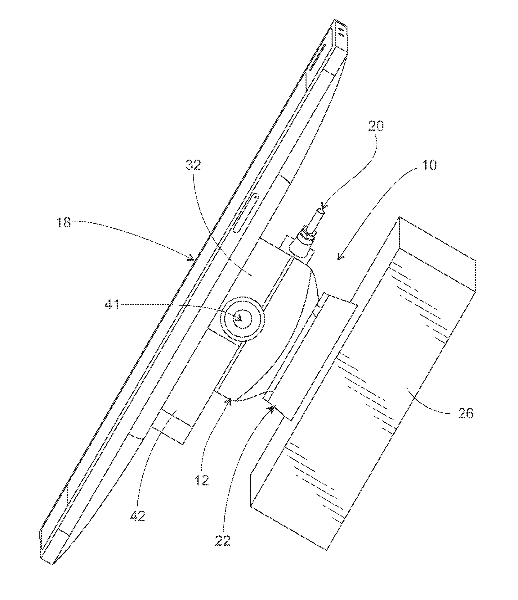
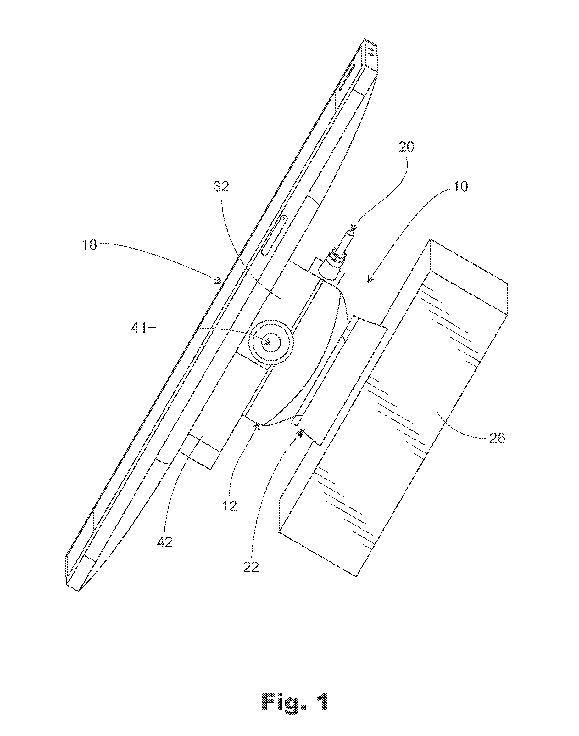
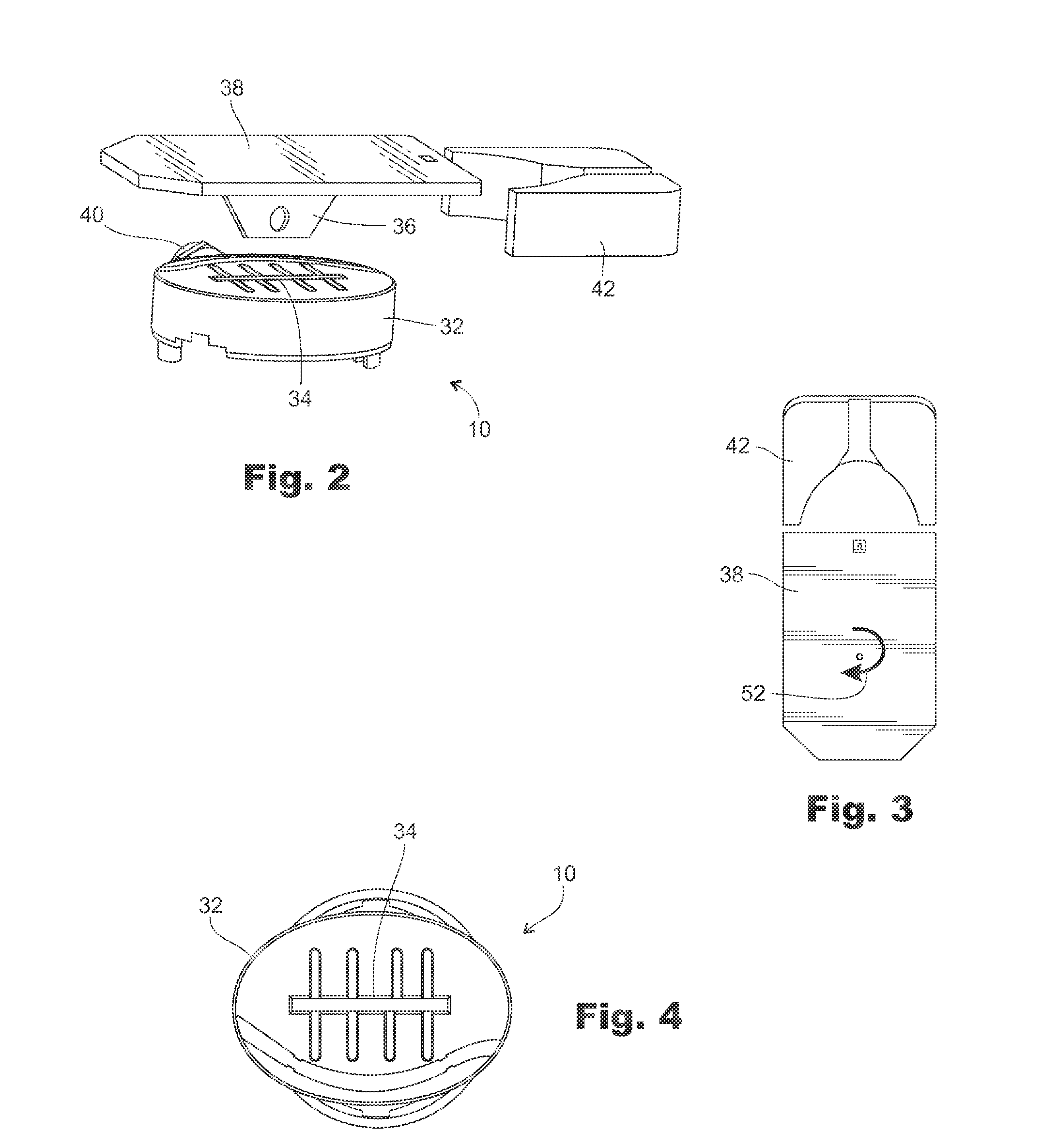
[0033]Referring now to the drawings, and first to FIG. 1, shown generally at 10 is a rotational mount constructed in accordance with a preferred embodiment of the invention. The rotational mount 10 includes an upper body portion, indicated generally by arrow 12, and a lower body portion that is indicated generally at 14 (see FIG. 9). The lower body portion 14 is generally cylindrical in shape and is sometimes referred to herein as the “lower cylindrical portion 14.” The upper and lower body portions 12, 14 may be manufactured in many different ways but, preferably, they are molded as an integrated piece during the fabrication process.

[0034]The upper body portion 12 carries an electronics control board (“ECB”), indicated generally at 16 in exploded view FIG. 10. The ECB 16 typically carries the electronics necessary to supply power or security functions to a hand-held device (indicated generally at 18 in the various drawing figures). The functions of the ECB 16 are generally known in...


PUM

PropertyMeasurementUnit
rotationaaaaaaaaaa
angleaaaaaaaaaa
weightaaaaaaaaaa

Abstract

The invention is a rotational mount for use in displaying hand-held consumer electronics in a retail environment. The rotational mount allows the hand-held to freely pivot in rotation on the display. The mount may automatically return to an initial orientation.

Description

TECHNICAL FIELD[0001]The invention disclosed here relates to displays for merchandise, in general, and hand-held consumer electronic devices, in particular. More specifically, the invention relates to a display that allows hand-helds to be turned or rotated on the display and then return to an initial or original rotational orientation when released.BACKGROUND OF THE INVENTION[0002]It is common to display various types of electronic devices (cell phones, cameras, PDAs, tablet devices, etc.) in a secured fashion on a countertop in a store. Often times, the device is mounted to a display post, sometimes with a tether or other mechanical means that secures the device to the post. Depending on the specific device, sometimes the device is mounted to a post in a way that allows the device to be turned or rotated without lifting it. Various kinds of security sensors are commonly used on the display.[0003]Smart phones and tablet devices have rectangular display screens that adjust the orien...

Claims


Application Information

Patent Timeline
Patent Type & Authority Applications(United States)
IPC IPC(8): H05K7/14B23P17/04A47F1/04
CPCA47F7/024F16M11/041F16M11/105F16M11/2014Y10T29/49826F16M13/00F16M13/02F16M2200/041F16M2200/08F16M11/2028
Inventor WHEELER, WADENIDEROST, DONALDALEXANDER, CHRISTOPHERPETERS, RON
Owner MOBILE TECH
Features
  • Generate Ideas
  • Intellectual Property
  • Life Sciences
  • Materials
  • Tech Scout
  • Unparalleled Data Quality
  • Higher Quality Content
  • 60% Fewer Hallucinations
Learn More