
Extending Filter Basket

Inactive Publication Date: 2013-01-31
GREEN PLANET SOLUTIONS
View PDF13 Cites 19 Cited by
  • Summary
  • Abstract
  • Description
  • Claims
  • Application Information

AI Technical Summary

Benefits of technology

The patent describes a mesh filter basket that can be placed inside a fryer to cook food. The basket allows the cooking liquid to pass through its wire mesh and cook the food, while keeping food particles in the fryer basket. The patent also describes a method for using the mesh filter basket in a fryer to cook food efficiently. The technical effect of this invention is to provide a convenient and efficient way to cook food in a fryer, while keeping it clean and easy to remove.

Problems solved by technology

The heat from the cooking liquid may cause the food to cook.
The food particles may remain in the cooking liquid over repeated cooking cycles, may become carbonized, and may negatively affect the flavor of foods cooked during a subsequent cooking cycle.
The buildup of such food particles may result in cooking liquid that is unusable for cooking and must be changed after a few frying cycles.

Method used


Image

  • Extending Filter Basket
  • Extending Filter Basket
  • Extending Filter Basket

Examples


second embodiment

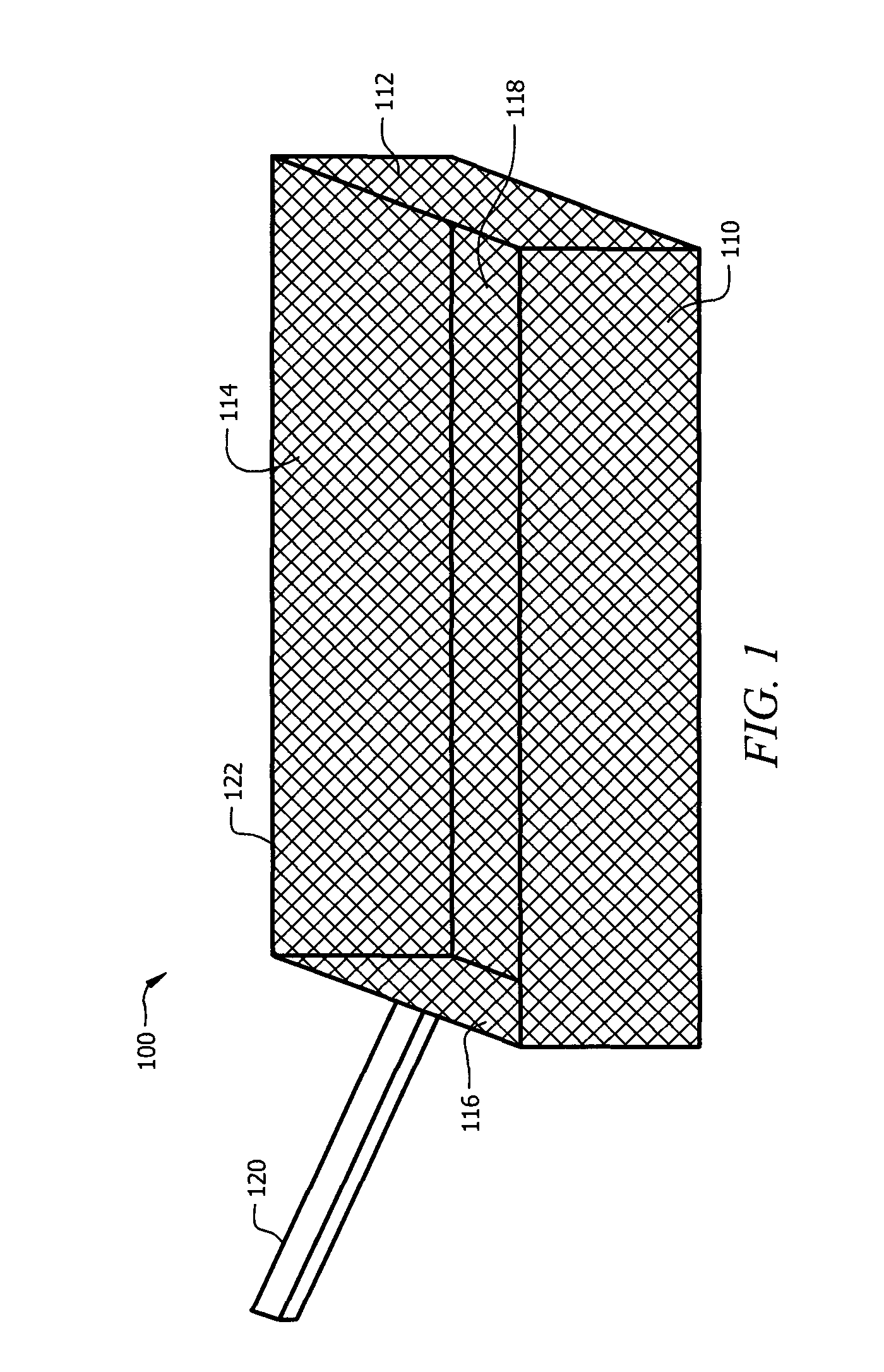
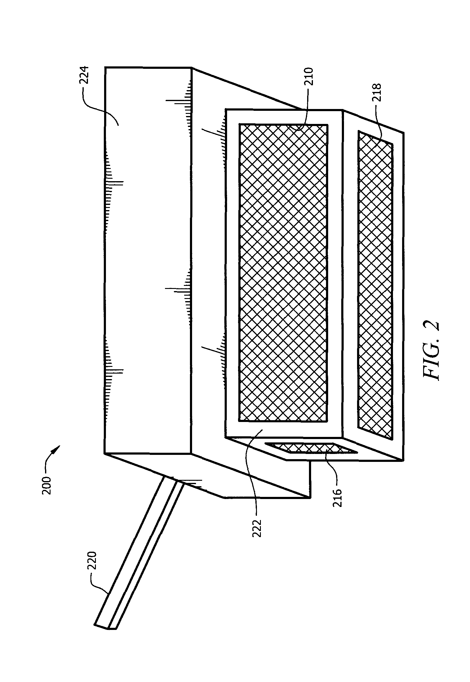
[0023]FIG. 2 is a general perspective view of a mesh filter basket 200. The mesh filter basket 200 may be generally rectangular and may comprise an upper frame 224, a lower frame 222 comprising lower longitudinal mesh side walls 210 and lower latitudinal mesh side walls 216, a mesh base 218, and a handle 220. The upper frame 224 and the lower frame 222 may be constructed of substantially rigid stainless steel, sheet metal, copper, or other materials that maintain a substantially rigid structure at temperatures commonly used for frying (e.g. less than about 500 degrees Fahrenheit). The upper frame 224 may be connected to the lower frame 222 and the handle 220 as shown in FIG. 2. The lower frame 222 may be connected to and provide support to the mesh side walls 216 and mesh base 218. The mesh side walls 216, mesh base 218, and handle 220 may be substantially similar to mesh side walls 112, mesh base 118, and handle 120, respectively.

third embodiment

[0024]FIG. 3 is a general perspective view of a mesh filter basket 300. The mesh filter basket 300 may be generally cylindrical and may comprise an upper frame 324, a lower frame 322, mesh base 318, a mesh side wall 310, and a handle 320. The upper frame 324 may comprise a substantially circular shape and may be connected to the mesh side wall 310. The mesh side wall 310 may be substantially cylindrical and may be connected to the lower frame 322. The lower frame 322 may be substantially circular. The handle 320 may comprise a semicircular shape and may be connected to the upper frame 324 in at least two locations as shown in FIG. 3. The components of mesh filter basket 300 comprise similar materials of analogous components in mesh filter baskets 100 and / or 200.

fourth embodiment

[0025]FIG. 4 is a general perspective view of a mesh filter basket 400. Mesh filter basket 400 may be generally cylindrical and may comprise an upper frame 424, a lower frame 422, a mesh base 418, a mesh side wall 410, and a handle 420, which may be substantially similar to upper frame 324, lower frame 322, mesh base 318, mesh side wall 310, and a handle 320, respectively. Handle 420 may be comprise a rigid material and may extend longitudinally from upper frame 424. The components of mesh filter basket 400 may comprise similar materials of analogous components in mesh filter baskets 100, 200, and / or 300.


PUM


Abstract

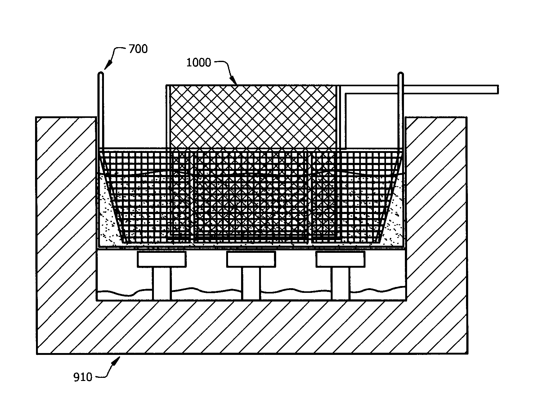
A mesh filter basket comprising a frame, and a wire mesh attached to the frame, wherein the mesh filter basket is configured to be placed inside a fryer comprising cooking liquid, wherein the mesh filter basket is configured to receive a fryer basket comprising food, wherein the mesh filter basket is configured to allow the cooking liquid to pass through the mesh and cook the food in the fryer basket, and wherein the mesh filter basket is configured to retain food particles escaping the fryer basket.

Description

CROSS-REFERENCE TO RELATED APPLICATIONS[0001]This application is a continuation in part of prior U.S. patent application Ser. No. 12 / 467,514, filed on May 18, 2009, which claims priority to U.S. Provisional Patent Application No. 61 / 055,495 filed on May 23, 2008, both of which are incorporated herein by reference as if reproduced in their entirety.STATEMENT REGARDING FEDERALLY SPONSORED RESEARCH OR DEVELOPMENT[0002]Not applicable.REFERENCE TO A MICROFICHE APPENDIX[0003]Not applicable.BACKGROUND[0004]Restaurants may employ fryers to cook fried foods. Cooking liquid (e.g. cooking oil, water, etc.) may be poured into a fryer and heated. The food that is to be cooked (e.g. fried) may be battered and placed in a basket. The basket may then be lowered into the fryer. The basket may be constructed to allow the heated cooking liquid to come into contact with the food. The heat from the cooking liquid may cause the food to cook. The basket containing the food may then be removed from the fry...

Claims


Application Information

Patent Timeline
IPC IPC(8): A47J37/12A23L1/01A23L5/10
CPCA47J37/1295A47J37/1271A47J37/1223
Inventor KETTER, JR., CHARLESMATHES, MARK
Owner GREEN PLANET SOLUTIONS
Learn More