Lighting device

a technology of leds and light fixtures, which is applied in the direction of spectral modifiers, metal-working apparatus, light sources, etc., can solve the problems of limiting the flexibility of the manufacturing and installation of leds and other functionalities of lighting devices into tubes, and achieves the effect of being convenient and flexibl

Active Publication Date: 2013-02-07
KONINKLIJKE PHILIPS ELECTRONICS NV
View PDF5 Cites 114 Cited by
  • Summary
  • Abstract
  • Description
  • Claims
  • Application Information

AI Technical Summary

Benefits of technology

[0003]It is an object of the present invention to provide an alternative and improved lighting device which can be manufactured and assembled in an inexpensive and flexible manner.

Problems solved by technology

The tube is rigid and typically made of a sturdy plastic or glass, which limits the flexibility of the manufacturing and installation of the LEDs and other functionalities of the lighting device into the tube.

Method used


Image

  • Lighting device
  • Lighting device
  • Lighting device

Examples


Embodiment Construction

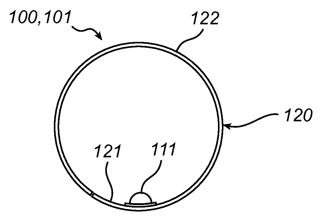
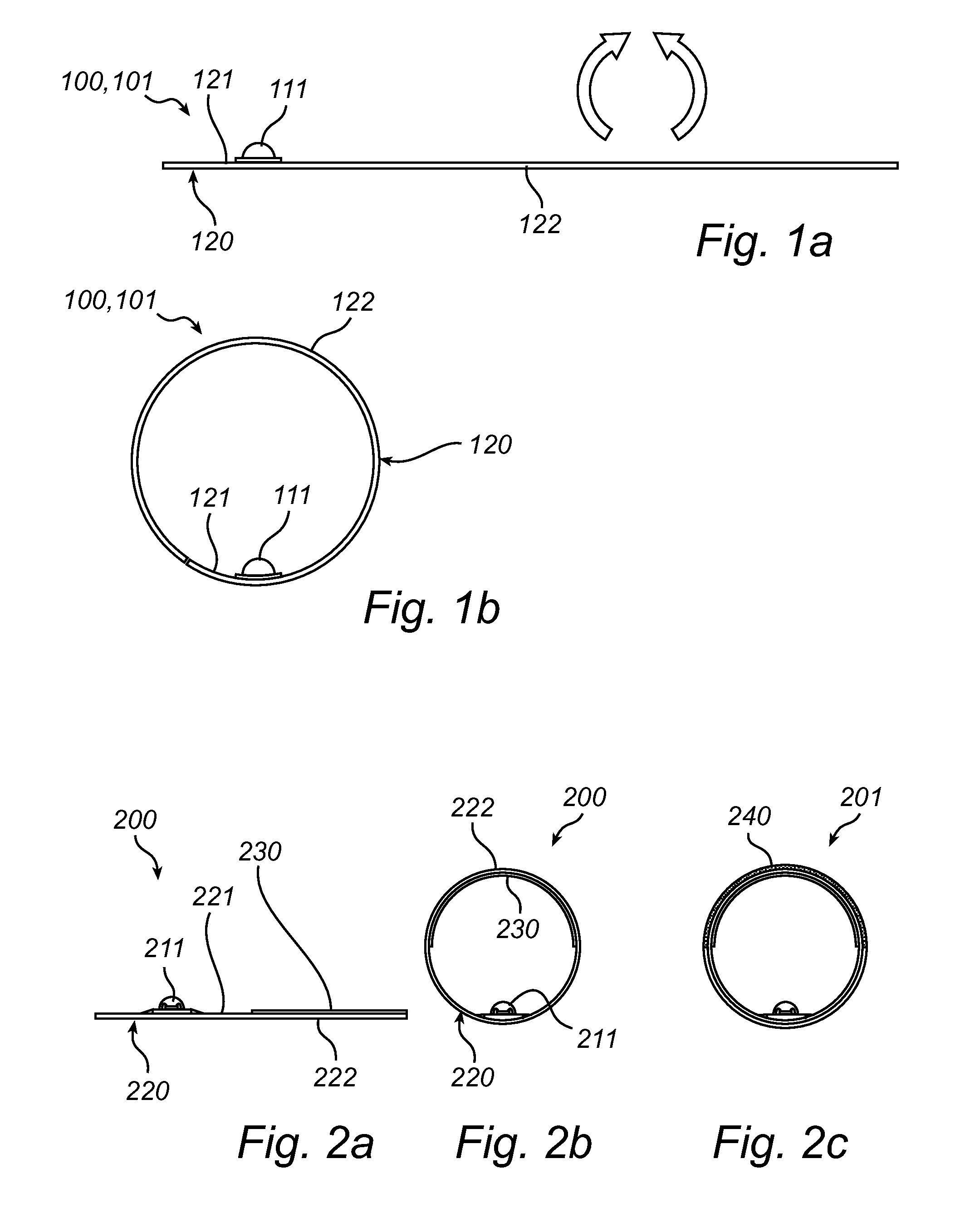
[0028]A lighting device 101 according to the present inventive concept is illustrated in FIG. 1a in an unrolled state. The lighting device comprises a sheet assembly 100 which is based on a carrier foil 120 which here is a transparent flexible foil. The transparent carrier foil is typically made of a suitable polymer, which is either clear or diffuse. Further, the carrier foil may be a stacked foil, comprising multiple layers. A light source 111, here comprising a linear array of light emitting diodes (LED) for light generation, is arranged on an upper side 121 of the carrier foil 120. The light source 111 is composed of a printed circuit board (PCB) with packaged LEDs. The light source 111 is attached to the carrier foil 120 by means of an adhesive, such as a silicone or a two-component thermal paste. Any suitable adhesive, which preferably has good thermal conductivity is applicable. Alternatively the light source may be attached by means of mechanical fixation such as a coiled sp...


PUM

PropertyMeasurementUnit
flexibleaaaaaaaaaa
transparentaaaaaaaaaa
translucentaaaaaaaaaa

Abstract

There is provided a lighting device and a method to manufacture such a lighting device. The inventive concept is based on manufacturing a lighting device on an at least partly flexible sheet assembly which is rolled into a tube, such that the light source of the lighting device is arranged within the tube. The flexible sheet assembly is arranged such that the tube provides a light mixing chamber and light exit surface for the lighting device. Thus, the tube shaped lighting device instantly delivers the necessary optical and mechanical properties for easy assembly and the functionality of a light engine.

Description

FIELD OF THE INVENTION[0001]The invention relates generally to lighting devices, and more specifically to a lighting device comprising at least one light source for providing light arranged in an elongated hollow, tubular member with a light exit surface for light provided by the light source. The invention further relates to a method for manufacturing such a lighting device.BACKGROUND OF THE INVENTION[0002]Recently, as lighting devices comprising light emitting diodes (LEDs) are used as replacement to traditional lighting devices such as conventional light bulbs, they also start being targeted at application of fluorescent tubes. U.S. Pat. No. 7,114,830 B2 discloses such a lighting device, which comprises an elongated, hollow, rigid tube into which a plurality of LEDs are inserted. The elongated, hollow tube provides a light mixing chamber with a light exit surface for light provided by the LEDs. The tube is rigid and typically made of a sturdy plastic or glass, which limits the fl...

Claims


Application Information

Patent Timeline
Patent Type & Authority Applications(United States)
IPC IPC(8): F21V8/00B23P11/00
CPCF21V1/06Y10T29/49826F21V31/04F21K9/56F21K9/90F21S4/003F21V3/0409F21V7/005F21V9/16F21Y2101/02F21Y2103/003H05K1/028H05K2201/0108H05K2201/051H05K2201/10106H05K2201/2054F21V7/18F21V13/14F21S4/20F21K9/64F21Y2103/10F21Y2115/10F21V3/06F21V7/30F21V9/32
Inventor VAN DER WEL, PIETER JOSEPH CLARADINGEMANS, ANTONIUS PETRUS MARINUS
Owner KONINKLIJKE PHILIPS ELECTRONICS NV
Why Eureka
Try Eureka