Charger

a secondary battery and charging time technology, applied in the field of chargers, can solve the problems of increasing the possibility of erroneous determination, increasing the possibility of measurement errors, and limited charging times of secondary batteries repeatedly used, and achieve the effect of accurately determining the deterioration of secondary batteries

Active Publication Date: 2013-03-14
PANASONIC INTELLECTUAL PROPERTY MANAGEMENT CO LTD
View PDF2 Cites 33 Cited by
  • Summary
  • Abstract
  • Description
  • Claims
  • Application Information

AI Technical Summary

Benefits of technology

[0017]The charger in accordance with the embodiment of the present invention is capable of more accurately determining the deterioration of the secondary battery regardless of the type of secondary battery or the remaining capacity of the secondary battery before the initiation of charging.

Problems solved by technology

Accordingly, charging times of the secondary battery repeatedly used are limited.
However, since the charging device described in JP2007-24541A uses the voltage before the initiation of charging to determine the life span, the possibility of erroneous determination may be increases because of the type or the remaining capacity of the secondary battery.
In addition, the battery deterioration measuring device described in JP2008-123961 needs to accurately measure the charging current and voltage of the secondary battery and to calculate the internal resistance, and accordingly, there is a possibility of measurement errors.

Method used


Image

  • Charger
  • Charger
  • Charger

Examples


first embodiment

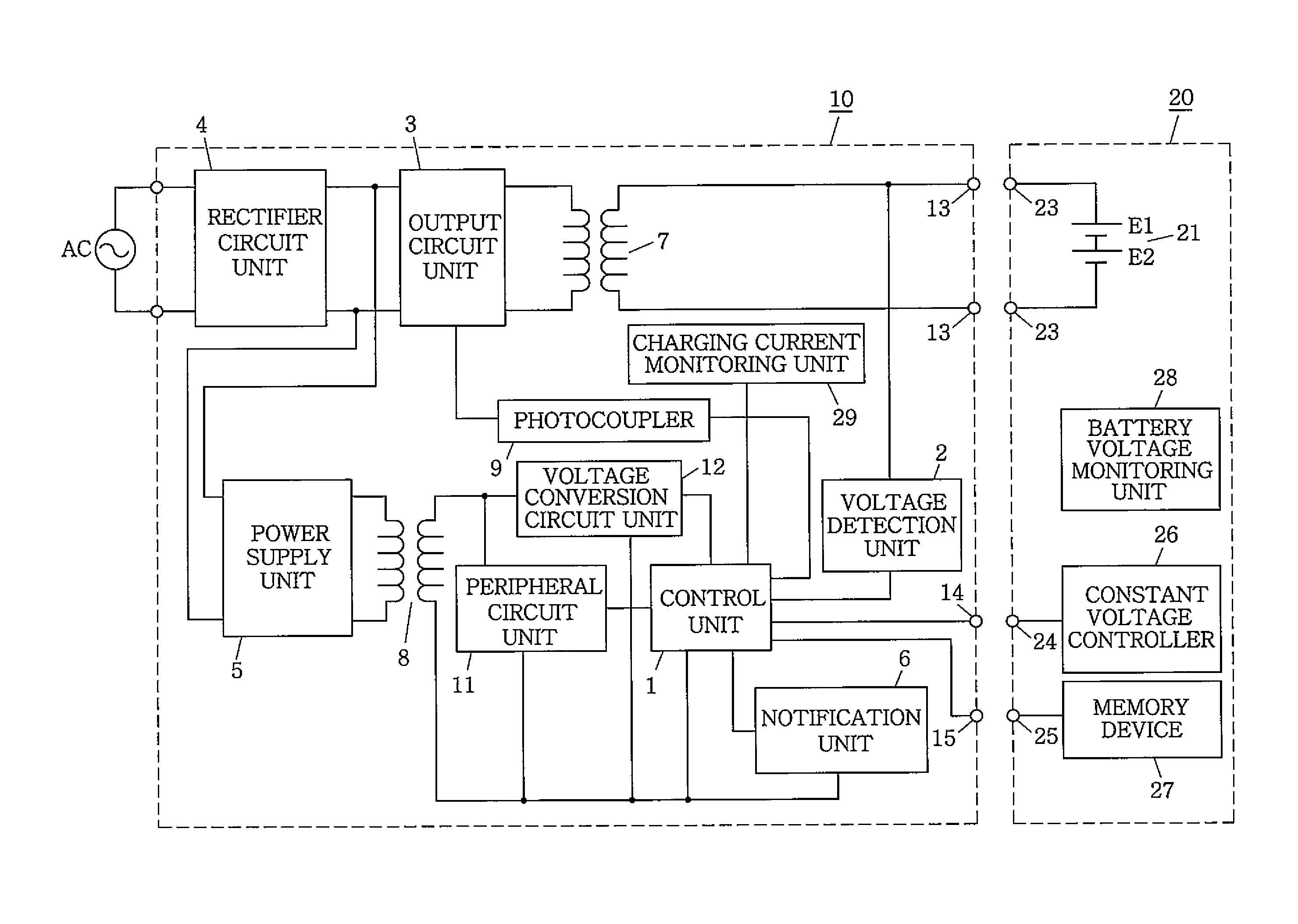
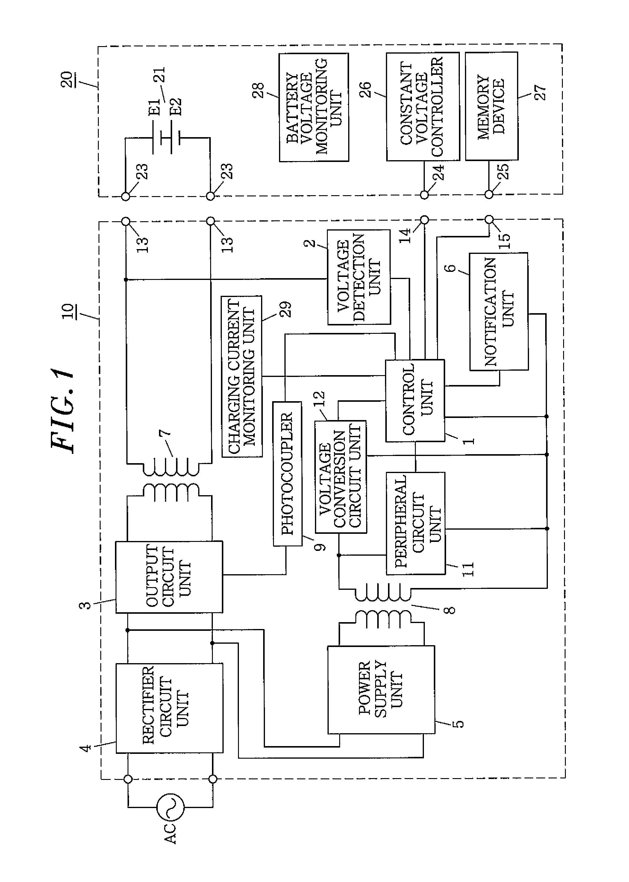
[0025]Referring to FIGS. 1 to 3, a charger 10 and a battery pack 20 connected thereto in accordance with the present embodiment will be described. The same reference numerals will be used to designate the same components throughout the drawings, and redundant descriptions thereof will be omitted.

[0026]The charger 10 in accordance with the present embodiment, as shown in FIG. 1, charges a secondary battery 21 using an external power source AC such as a commercial power source or the like. The secondary battery 21 is contained in the battery pack 20 that can be detachably attached to the housing (not shown) of the charger 10. Two small batteries E1 and E2 that are electrically connected in series are used as the secondary battery 21.

[0027]The charger 10 in accordance with the present embodiment includes an output circuit unit 3 for outputting a charging current to the secondary battery 21 and a voltage detection unit 2 for detecting a voltage of the secondary battery 21. The charger 1...

second embodiment

[0086]Although the charger 10 in accordance with the present embodiment uses the voltage drop values during the constant current charging in the first embodiment without change, there is difference in that the charger 10 in accordance with the present embodiment determines whether or not the secondary battery 21 has deteriorated by excluding the deviation in the voltage drop values of the secondary batteries 21 of respective battery packs 20 in the initial phase in which the number of charging times of the secondary battery is smaller than a specific number.

[0087]Further, the charger 10 in accordance with the present embodiment and a battery pack 20 connected to the charger 10 have the same circuit configuration as the charger 10 and battery pack 20 in accordance with the first embodiment shown in FIG. 1. The charger 10 in accordance with the present embodiment is different from the charger 10 of the first embodiment in a control program of the control unit 1 that performs the calcu...


PUM


Abstract

A charger includes an output circuit unit to output a charging current to a secondary battery, a voltage detection unit to detect a voltage of the secondary battery, and a control unit to control the output circuit unit, whereby constant current charging and constant voltage charging are performed. The control unit decreases a constant current value of the charging current by stages during the constant current charging and determines that the secondary battery has deteriorated by using a first voltage drop value of the secondary battery occurring upon first conversion and a second voltage drop value of the secondary battery occurring upon second conversion.

Description

FIELD OF THE INVENTION[0001]The present invention relates to a charger.BACKGROUND OF THE INVENTION[0002]Conventionally, a secondary battery has been used as a power source for a variety of types of a portable device or the like. As the number of charge and discharge cycles of a secondary battery increases, the discharge capacity thereof decreases. Accordingly, charging times of the secondary battery repeatedly used are limited. For this reason, some chargers that charge secondary batteries are configured to determine life spans of the secondary batteries when charging them.[0003]This type of the charger includes a charging device that includes a battery voltage detection circuit configured to detect a battery voltage of a battery pack provided with a secondary battery and battery voltage gradient calculation means configured to calculate a battery voltage gradient based on the detected battery voltage and a battery voltage before a predetermined time (see, e.g., Japanese Patent Appl...

Claims


Application Information

Patent Timeline
Patent Type & Authority Applications(United States)
IPC IPC(8): H02J7/00
CPCH02J7/0047H02J7/045H02J7/04H02J7/0049H02J7/00714H02J7/007182
Inventor KAWAI, AKIRAIKEDA, MASAKISAKAUE, MASAAKIOHASHI, TOSHIHARU
Owner PANASONIC INTELLECTUAL PROPERTY MANAGEMENT CO LTD
Why Eureka
Try Eureka