
Organic light emitting display device for compensating deterioration of a pixel and method of driving the same

a display device and organic light technology, applied in the direction of static indicating devices, instruments, etc., can solve the problems of affecting so as to accurately compensate the deterioration of pixel accuracy and improve the display quality of organic light emitting display devices

Active Publication Date: 2018-05-29
SAMSUNG DISPLAY CO LTD
View PDF5 Cites 2 Cited by
  • Summary
  • Abstract
  • Description
  • Claims
  • Application Information

AI Technical Summary

Benefits of technology

This patent describes an organic light emitting display device that can improve its quality. The device uses a modeling voltage map to adjust for variations in current flow through pixels. This allows the device to accurately compensate for any deterioration of the pixels. The method of driving the device also improves its display quality.

Problems solved by technology

When the deterioration of the pixel occurs, the display quality can decrease, and afterimage can occur because a luminance of the deteriorated pixel decreases.
However, when the sensing current is sensed using the fixed sensing reference voltage, error of the current variation may occur because of a characteristic variation of the pixels.
Accordingly, the organic light emitting display device might not accurately compensate the deterioration of the pixel.

Method used


Image

  • Organic light emitting display device for compensating deterioration of a pixel and method of driving the same
  • Organic light emitting display device for compensating deterioration of a pixel and method of driving the same
  • Organic light emitting display device for compensating deterioration of a pixel and method of driving the same

Examples


example embodiment 1

[0075][Example Embodiment 1]

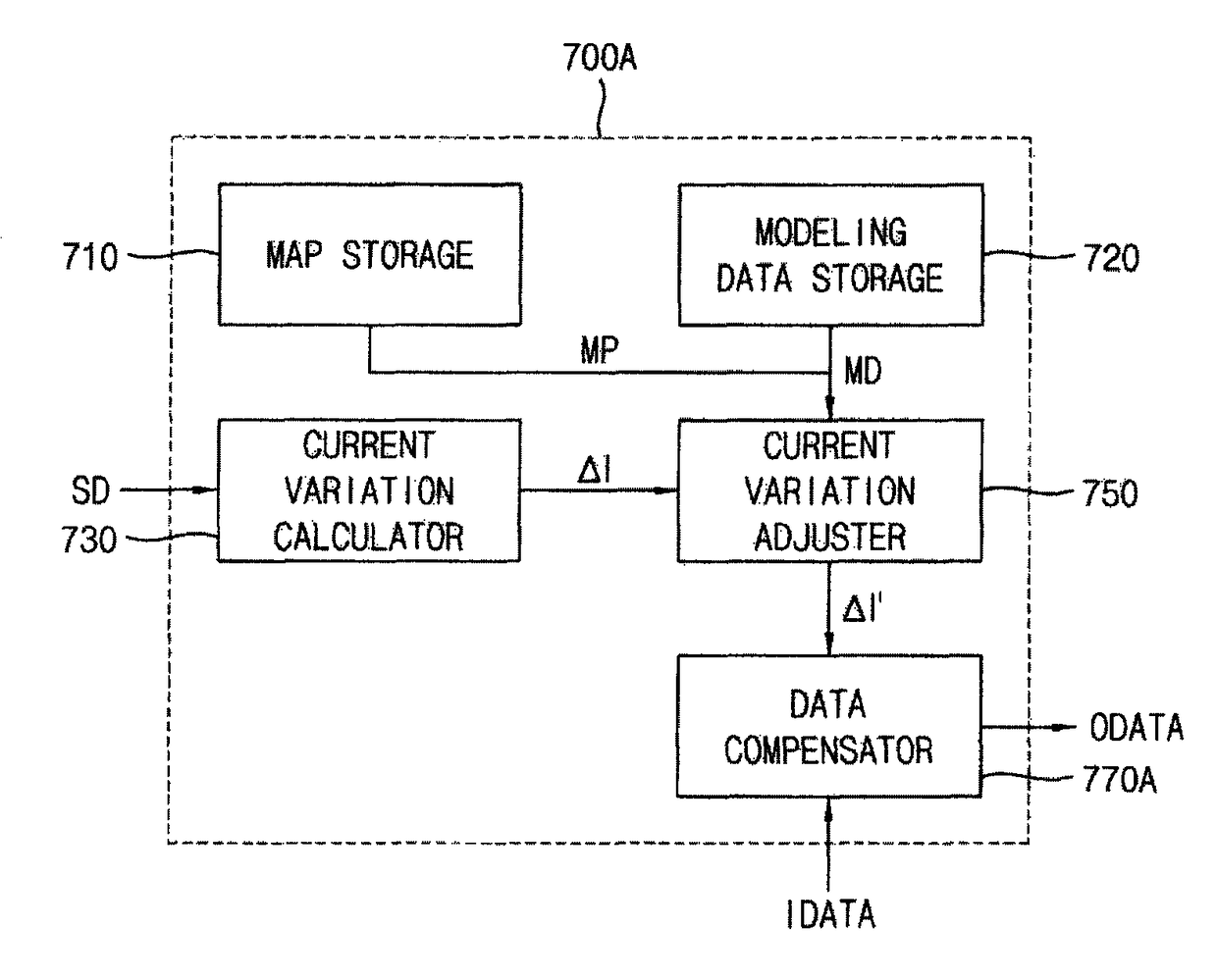
[0076]In the present embodiment, the sensing reference voltage VSET is 4V, the sensing current variation ΔI is 10%, and the first modeling voltage VMSET1 corresponding to a target pixel, which is derived from the modeling voltage map MP, is 4.1V. In this case, the first current variation adjustment value IA1 calculated using the modeling data MD is about 0.177% (i.e., 0.177%=(−0.1363*4.1+0.7367)%), and the second current variation adjustment value IA2 is about 0.191% (i.e., 0.191%=(−0.1363*4+0.7367)%). Therefore, the adjustment current variation ΔI′ is about 9.986% (i.e., 9.986%=(10+(0.177−0.191))%).

example embodiment 2

[0077][Example Embodiment 2]

[0078]In the present embodiment, the sensing reference voltage VSET is 4V, the sensing current variation ΔI is 10%, and the first modeling voltage VMSET1 corresponding to a target pixel, which is derived from the modeling voltage map MP, is 3.9V. In this case, the first current variation adjustment value IA1 calculated using the modeling data MD is about 0.205% (i.e., 0.205%=(−0.1363*3.9+0.7367)%), and the second current variation adjustment value IA2 is about 0.191% (i.e., 0.191%=0.191%=(−0.1363*4+0.7367)%). Therefore, the adjustment current variation ΔI′ is about 10.014% (i.e., 10.014%=(10+(0.205−0.191))%).

example embodiment 3

[0079][Example Embodiment 3]

[0080]In the present embodiment, the sensing reference voltage VSET is 4V, the sensing current variation ΔI is 10%, and the first modeling voltage VMSET1 corresponding to a target pixel, which is derived from the modeling voltage map MP, is 4V. In this case, the sensing current variation ΔI is not needed to be adjusted because the first modeling voltage VMSET1 equals to the sensing reference voltage. Therefore, the adjustment current variation ΔI′ is 10%.

[0081]The data compensator 770A may compensate the input image data IDATA based on the adjustment current variation ΔI′. For example, the data compensator 770A may calculate a luminance variation ΔL that occurs due to the deterioration of the pixel based on the adjustment current variation ΔI′. In one example embodiment, the data compensator 770A may calculate the luminance variation ΔL according to [Equation 2] below:

ΔL=Ka*ΔI′+Kb  [Equation 2]

[0082]where, ΔL is the luminance variation, Ka is a constant v...


PUM


Abstract

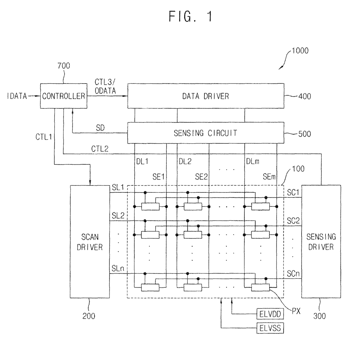
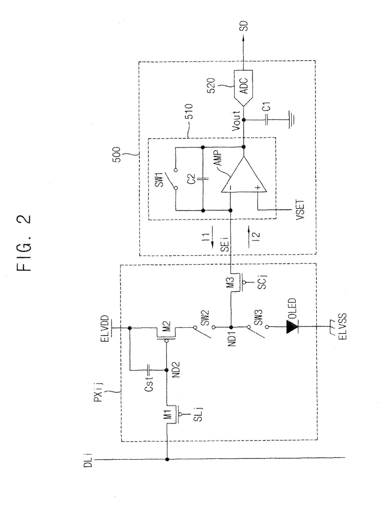
An organic light emitting display device includes a display panel including a plurality of pixels, a scan driver configured to provide a scan signal to the pixels, a data driver configured to provide a data signal to the pixels, a sensing circuit configured to sense a sensing current flowing through the pixels according to a sensing reference voltage applied to the pixels, and a controller configured to calculate a sensing current variation from the sensing current, and configured to adjust the sensing current variation based on a variation data of the pixels to compensate an input image data.

Description

CROSS REFERENCE TO RELATED APPLICATION[0001]This application claims priority to, and the benefit of, Korean patent Application No. 10-2015-0132984 filed on Sep. 21, 2015, the entire disclosure of which is hereby incorporated by reference herein in its entirety.BACKGROUND[0002]1. Field[0003]Example embodiments of the inventive concept relate to display devices, and a method of driving display devices, such as organic light emitting display devices.[0004]2. Description of the Related Art[0005]An organic light emitting diode (OLED) includes an organic layer between two electrodes, namely, between an anode and a cathode. Positive holes from the anode are combined with electrons from the cathode in the organic layer, which is between the anode and the cathode, to emit light. The OLED has a relatively wide viewing angle, a rapid response speed, is relatively thin, and low power consumption.[0006]Generally, in an organic light emitting display device including the OLED, a deterioration of ...

Claims


Application Information

Patent Timeline
Patent Type & Authority Patents(United States)
IPC IPC(8): G09G3/32G09G3/3275G09G3/20G09G3/3225G09G3/3233
CPCG09G3/2007G09G3/3225G09G3/3233G09G3/3275G09G2320/0233G09G2320/0295G09G2320/043G09G2320/045G09G2320/0693G09G2320/029G09G2300/0819G09G2300/0861
Inventor BAE, MIN-SEOKYANG, SU-MINPARK, JIN-WOOLEE, DONG-WON
Owner SAMSUNG DISPLAY CO LTD
Learn More