Dual latch electrical plug connector for electrical receptacle

Inactive Publication Date: 2013-03-21
HUBBELL INC
View PDF3 Cites 9 Cited by
  • Summary
  • Abstract
  • Description
  • Claims
  • Application Information

AI Technical Summary

Benefits of technology

[0006]Accordingly, it is a primary objective of the present invention to provide

Problems solved by technology

Gripping such a plug connector with three fingers can be difficult and cumbersome when working in confined areas.
Such existing plug connectors having a single latch to secure the plug connector to the aperture in an electrical receptacle are subject to accidental disengagement when installing the electrical receptacle in an electrical box.
Manipulation of the electrical receptacle during installation can put undue stress on the latch, thereby causing the plu

Method used


Image

  • Dual latch electrical plug connector for electrical receptacle
  • Dual latch electrical plug connector for electrical receptacle
  • Dual latch electrical plug connector for electrical receptacle

Examples


Example

[0029]Throughout the drawings, like reference numbers will be understood to refer to like parts, components and structures.

DETAILED DESCRIPTION OF THE EXEMPLARY EMBODIMENT

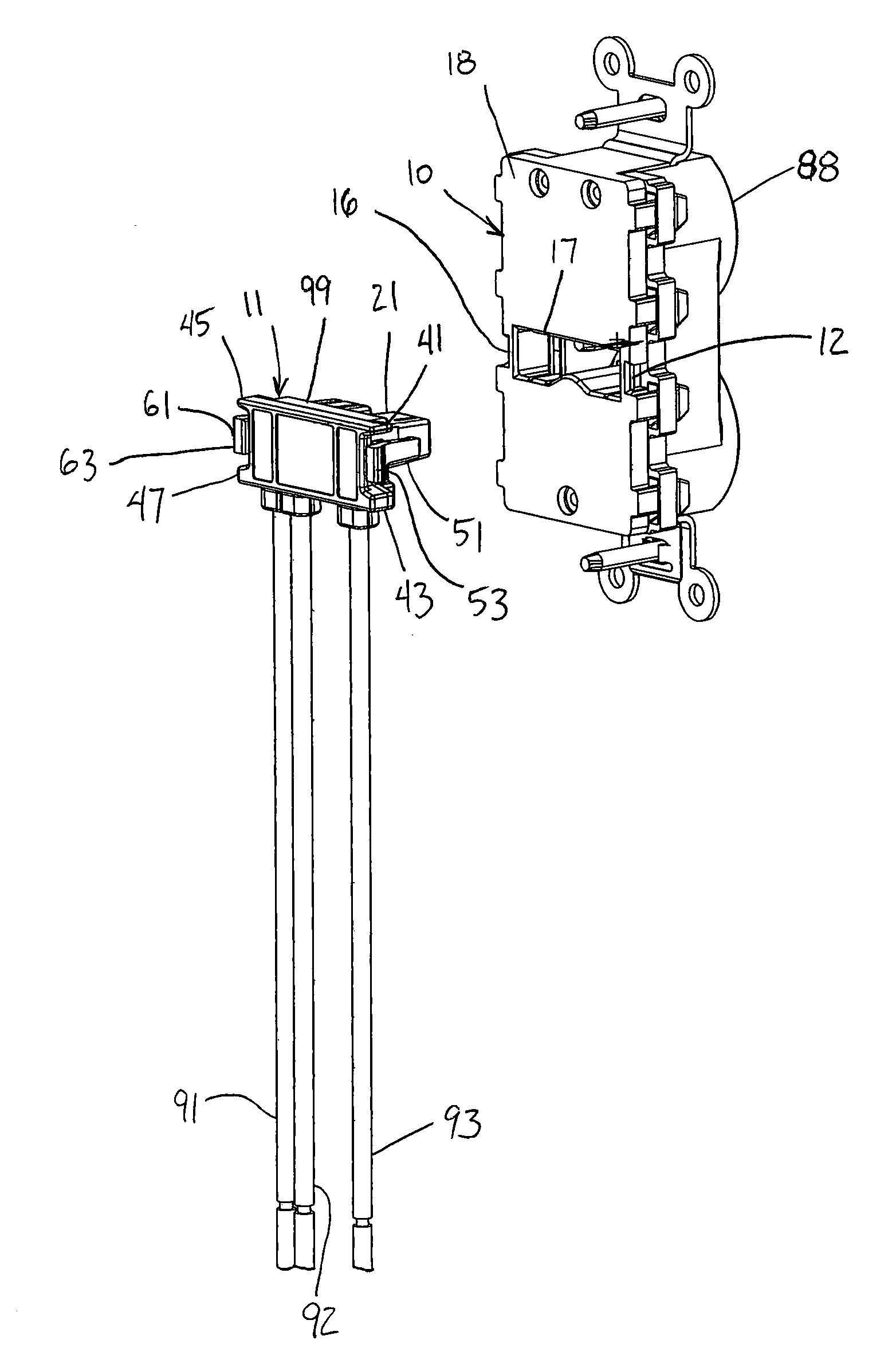
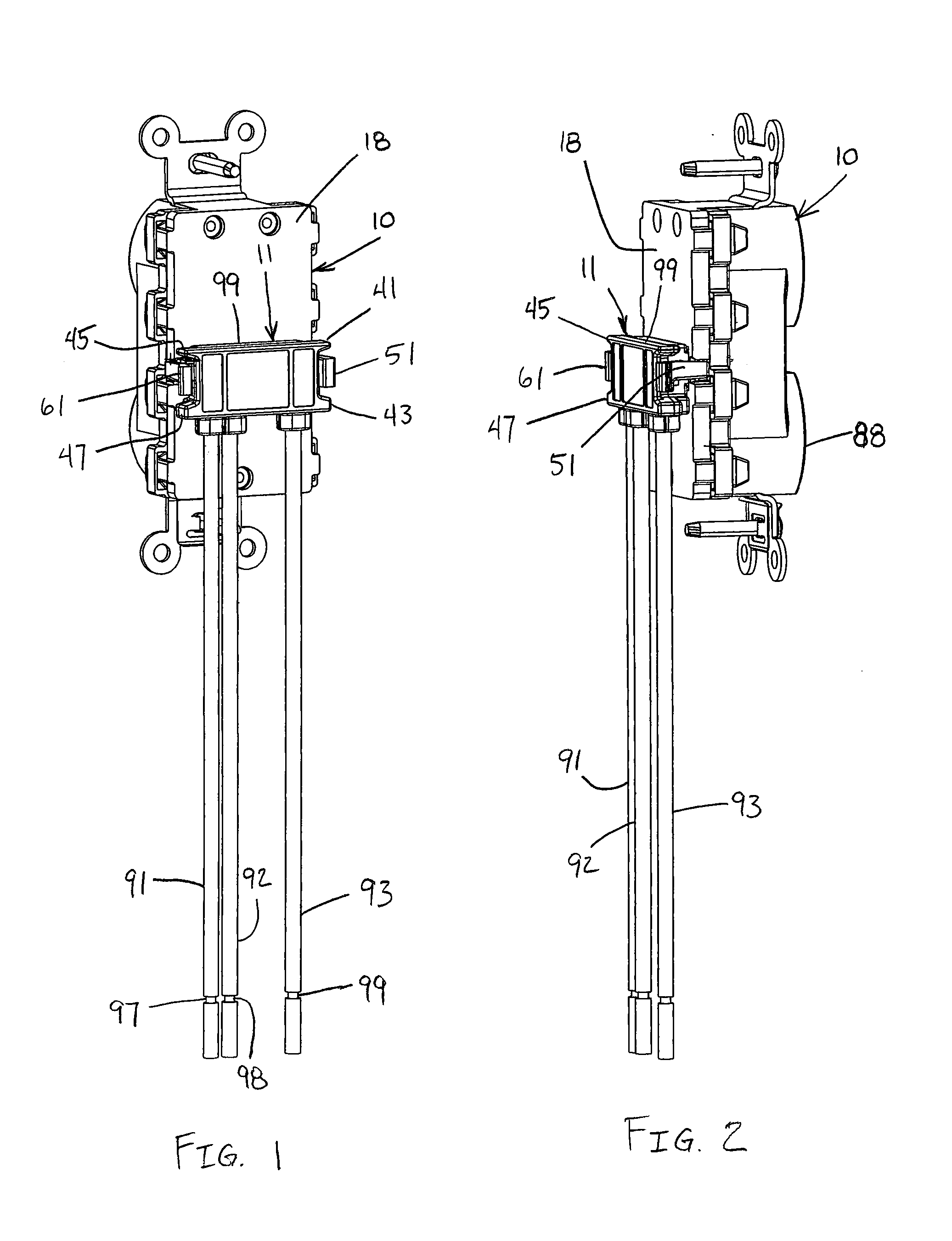
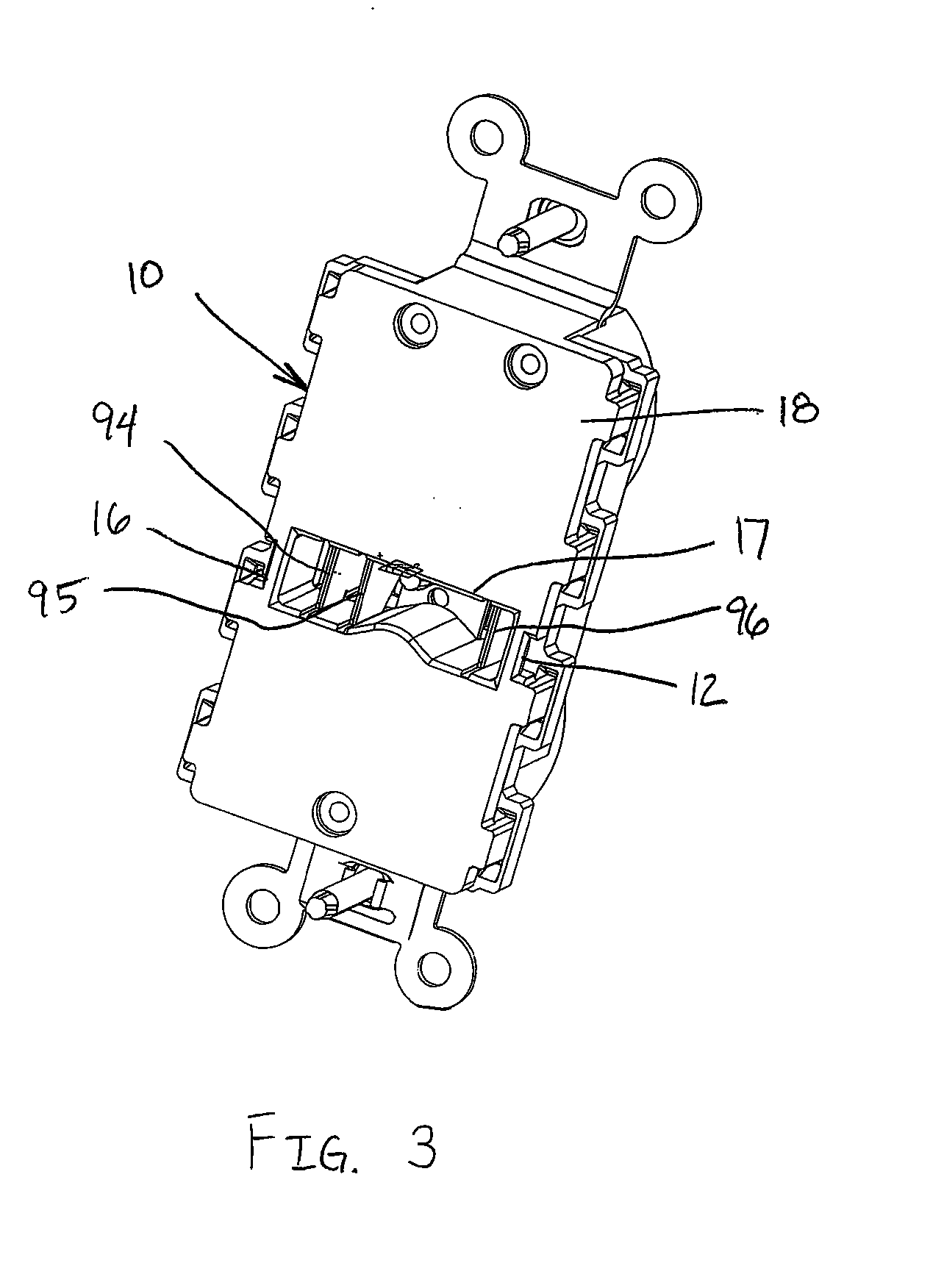
[0030]As shown in FIGS. 1-15, an electrical plug connector 11 includes a housing 21 and first and second latching arms 51 and 61, respectively. The plug connector 11 is receivable by an electrical wiring device, such as the electrical receptacle 10 shown in FIGS. 1-4 and 13. The plug connector 11 is connected to a snap-on type electrical receptacle 10, or any other snap-on type electrical wiring device, to convey electrical power to the electrical wiring device. Accordingly, an electrical apparatus (not shown) can be connected to the electrical receptacle 10 to receive power therefrom.

[0031]The plug connector 11 described has three wires 91, 92 and 93 connected thereto, as shown in FIGS. 1, 2 and 4-10, although the plug connector of the present invention is not so limited. Any suitable number of wires may be used a...


PUM


Abstract

An electrical plug connector includes a housing and first and second latching arms pivotally connected to the housing. First and second barriers are connected to the housing to protect the first latching arm. Third and fourth barriers are connected to the housing to protect the second latching arm. The barriers protect the first and second latching arms from being accidentally disengaged from an electrical wiring device by wires or other objects.

Description

FIELD OF THE INVENTION[0001]The present invention relates to an electrical connector having dual latches for connecting to an electrical device. More particularly, the present invention relates to an electrical connector having dual latches oppositely disposed to provide an ergonomic connector having a more secure connection with an electrical device. Still more particularly, the present invention relates to a dual-latch electrical connector having barriers to protect the latches from accidental disengagement from an electrical device.BACKGROUND OF THE INVENTION[0002]To facilitate connecting electrical wires to an electrical device, such as an electrical receptacle, some electrical devices have apertures in their rear faces for receiving plug connectors terminating a plurality of wires, as disclosed in U.S. Pat. No. 4,842,551 to Heimann. The wires terminated by the plug connector are connected to the existing wires in any suitable manner, such as by a clamp receptacle or a wire nut....

Claims


Application Information

Patent Timeline
IPC IPC(8): H01R13/62H01R13/627
CPCH01R13/6273
Inventor BAZAYEV, EDWARDSCANZILLO, THOMAS LOUIS
Owner HUBBELL INC
Why Eureka
Try Eureka