
Electronic device with thermoelectric cell module

a technology of thermoelectric cell and electronic device, which is applied in the manufacture/treatment of thermoelectric devices, electrical apparatus casings/cabinets/drawers, instruments, etc., can solve the problems of ineffective utilization of heat generated by electronic components, shortening the service life of electronic components, and affecting the processing speed of electronic devices

Inactive Publication Date: 2013-05-02
FU TAI HUA IND SHENZHEN +1
View PDF0 Cites 2 Cited by
  • Summary
  • Abstract
  • Description
  • Claims
  • Application Information

AI Technical Summary

Benefits of technology

The patent text is talking about how electronic devices generate heat and how important it is to dissipate that heat effectively to prevent damage to the components and improve performance. It also notes how energy is wasted when heat is not utilized effectively. The technical effect of the patent is to improve the cooling of electronic components to increase their lifespan and processing speed, while also ensuring effective use of the energy generated by the components.

Problems solved by technology

If the heat cannot be dissipated effectively in time, usage lifespan of the electronic components and a processing speed of the electronic device may be affected negatively.
Additionally, during usage of the electronic device, electrical energy is needed, while the heat generated by the electronic components is not utilized effectively.
Thus, energy is wasted.

Method used


Image

  • Electronic device with thermoelectric cell module
  • Electronic device with thermoelectric cell module
  • Electronic device with thermoelectric cell module

Examples


Embodiment Construction

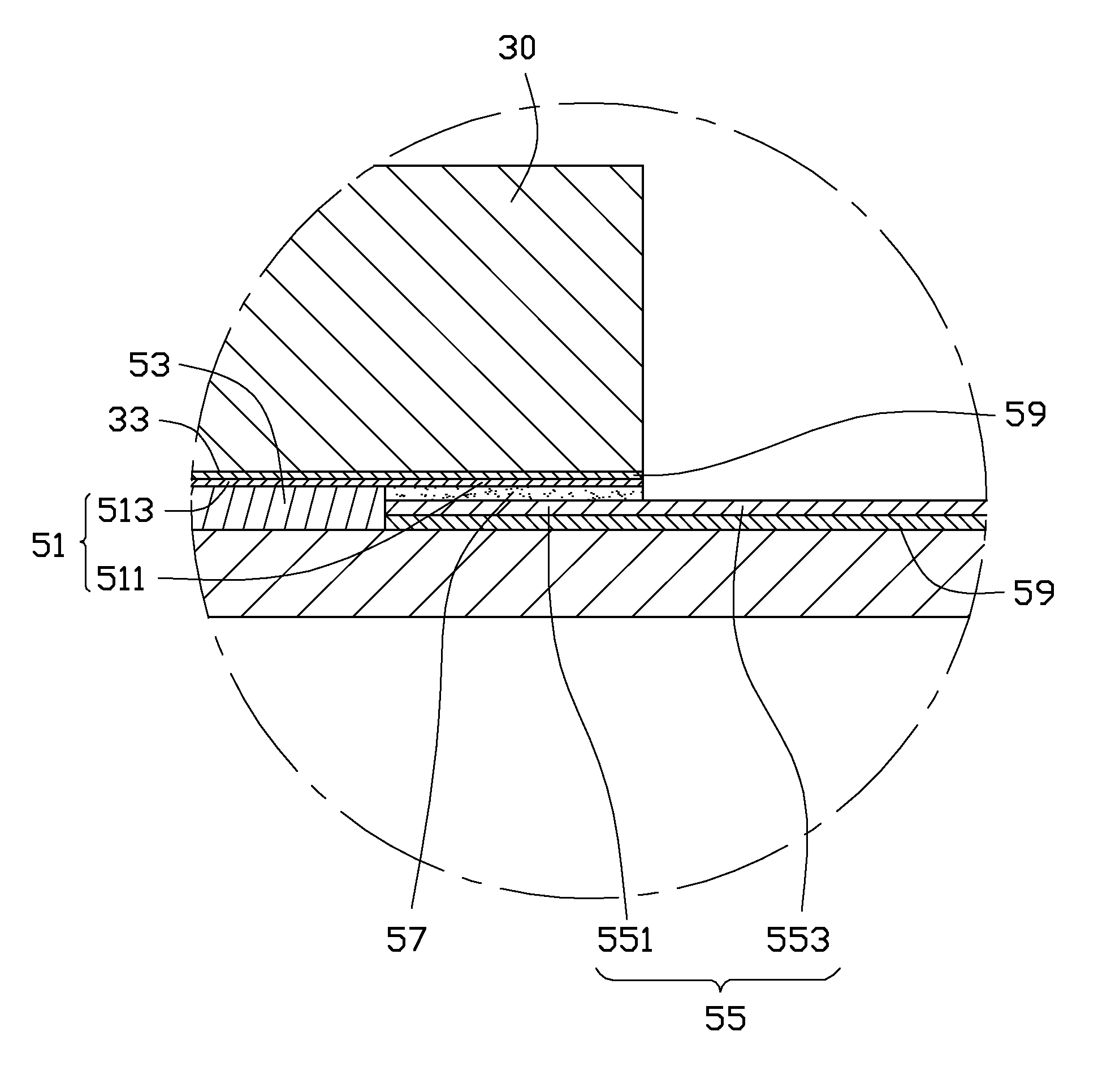
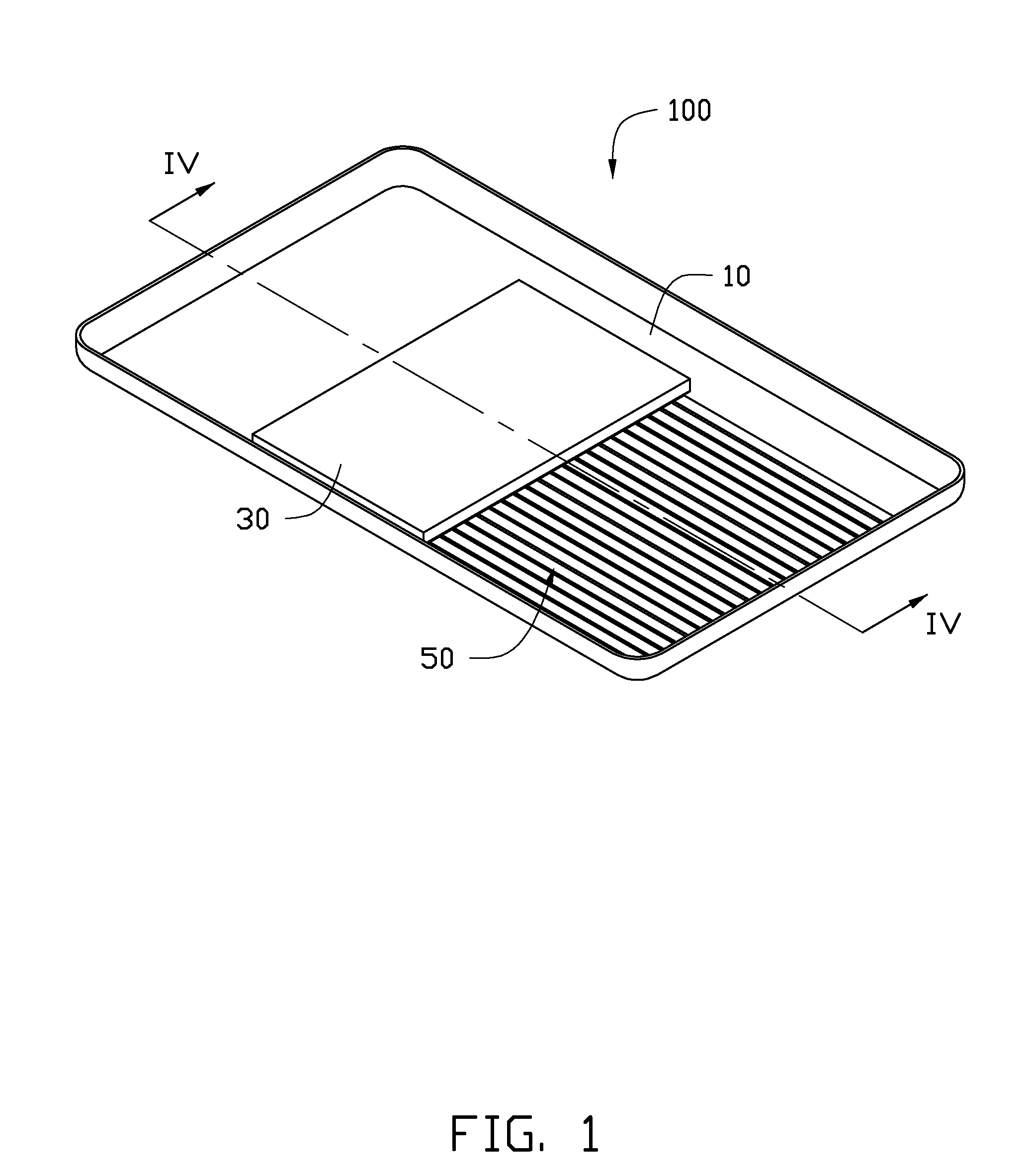
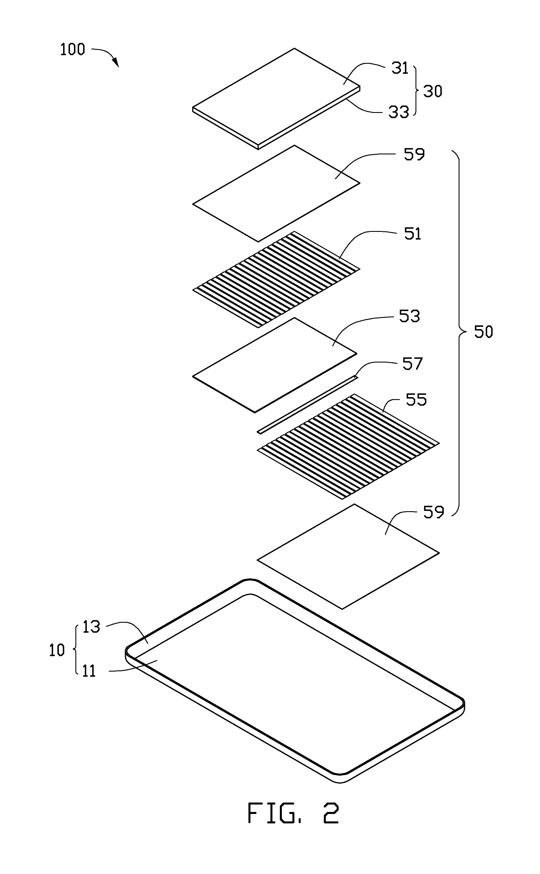
[0012]Referring to FIGS. 1 and 2, an embodiment of an electronic device 100 includes a bottom housing 10, a central processing unit (CPU) 30, and a thermoelectric cell module 50. The CPU 30 and the thermoelectric cell module 50 are securely placed on the bottom housing 10. The electronic device 100 can be a tablet computer, a mobile phone, a liquid crystal display, or a digital photo album. The electronic device 100 includes other various functional modules, such as a top cover (not shown) or a display module (not shown). However, for simplicity, only the components related to the thermoelectric cell module 50 are described herein.

[0013]The bottom housing 10 includes a base 11 and a peripheral wall 13 extending from a periphery of the base 11. The base 11 is substantially rectangular. The base 11 and the peripheral wall 13 cooperatively form a receiving space (not labeled) for receiving various functional modules.

[0014]The CPU 30 is mounted substantially on a center region of the ba...


PUM

PropertyMeasurementUnit
temperatureaaaaaaaaaa
thermoelectricaaaaaaaaaa
conductiveaaaaaaaaaa

Abstract

An electronic device includes a bottom housing, a heat-generating component placed on the bottom housing, and a thermoelectric cell module placed on the bottom housing and corresponding to the heat-generating component. The thermoelectric cell module includes a first thermoelectric sheet sensing a temperature of the heat-generating component, a second thermoelectric sheet sensing a temperature of the bottom housing, and a conductive member electrically connecting the first thermoelectric sheet and the second thermoelectric sheet.

Description

BACKGROUND[0001]1. Technical Field[0002]The present disclosure relates generally to electronic devices, especially, to an electronic device with a thermoelectric cell module.[0003]2. Description of Related Art[0004]During usage of an electronic device, electronic components, such as battery or CPU, generate heat. If the heat cannot be dissipated effectively in time, usage lifespan of the electronic components and a processing speed of the electronic device may be affected negatively. Additionally, during usage of the electronic device, electrical energy is needed, while the heat generated by the electronic components is not utilized effectively. Thus, energy is wasted.[0005]Therefore, there is room for improvement within the art.BRIEF DESCRIPTION OF THE DRAWINGS[0006]The elements in the drawings are not necessarily drawn to scale, the emphasis instead placed upon clearly illustrating the principles of the present disclosure. Moreover, in the drawings, like reference numerals designa...

Claims


Application Information

Patent Timeline
Patent Type & Authority Applications(United States)
IPC IPC(8): H01M14/00H01L35/04H01L35/32G06F1/16H10N10/17H10N10/81
CPCG06F1/1626H01L35/32G06F1/20G06F1/1635H10N10/17
Inventor SHI, FA-GUANGZHAO, JIAN-ZHOULIANG, YAN
Owner FU TAI HUA IND SHENZHEN
Learn More