
Vehicle seat

a technology for vehicles and seats, applied in vehicle components, pedestrian/occupant safety arrangements, vehicle arrangements, etc., can solve the problems of restricted rearward movement of occupants caused by side collision load receipt, and achieve the effect of preventing deformation, enhancing rigidity of force-receiving members, and facilitating the transmission of side collision load

Inactive Publication Date: 2013-05-09
TS TECH CO LTD +1
View PDF7 Cites 10 Cited by
  • Summary
  • Abstract
  • Description
  • Claims
  • Application Information

AI Technical Summary

Benefits of technology

The patent text describes a design that improves the rigidity and effectiveness of transmitting a side collision load in a vehicle. By using a force-receiving member and a load transmission part, the route of load transmission to the opposite side is set at a lower level, allowing for sufficient space between the frames for a person to move rearward in the event of a side collision. This design prevents deformation of the force-receiving member and enhances the rigidity of both the force-receiving member and the base frame, providing better load transmission.

Problems solved by technology

However, with the conventional technique, the diagonal brace disposed to extend diagonally from an upper portion of an inner surface of one side frame to a lower portion of an inner surface of the other side frame, and joined to these side frames; therefore, disadvantageously, rearward movement of an occupant which would be caused upon receipt of a side collision load is restricted.

Method used


Image

  • Vehicle seat
  • Vehicle seat
  • Vehicle seat

Examples


Embodiment Construction

[0021]Hereafter, a description will be given of one embodiment of the present invention with reference to the drawings.

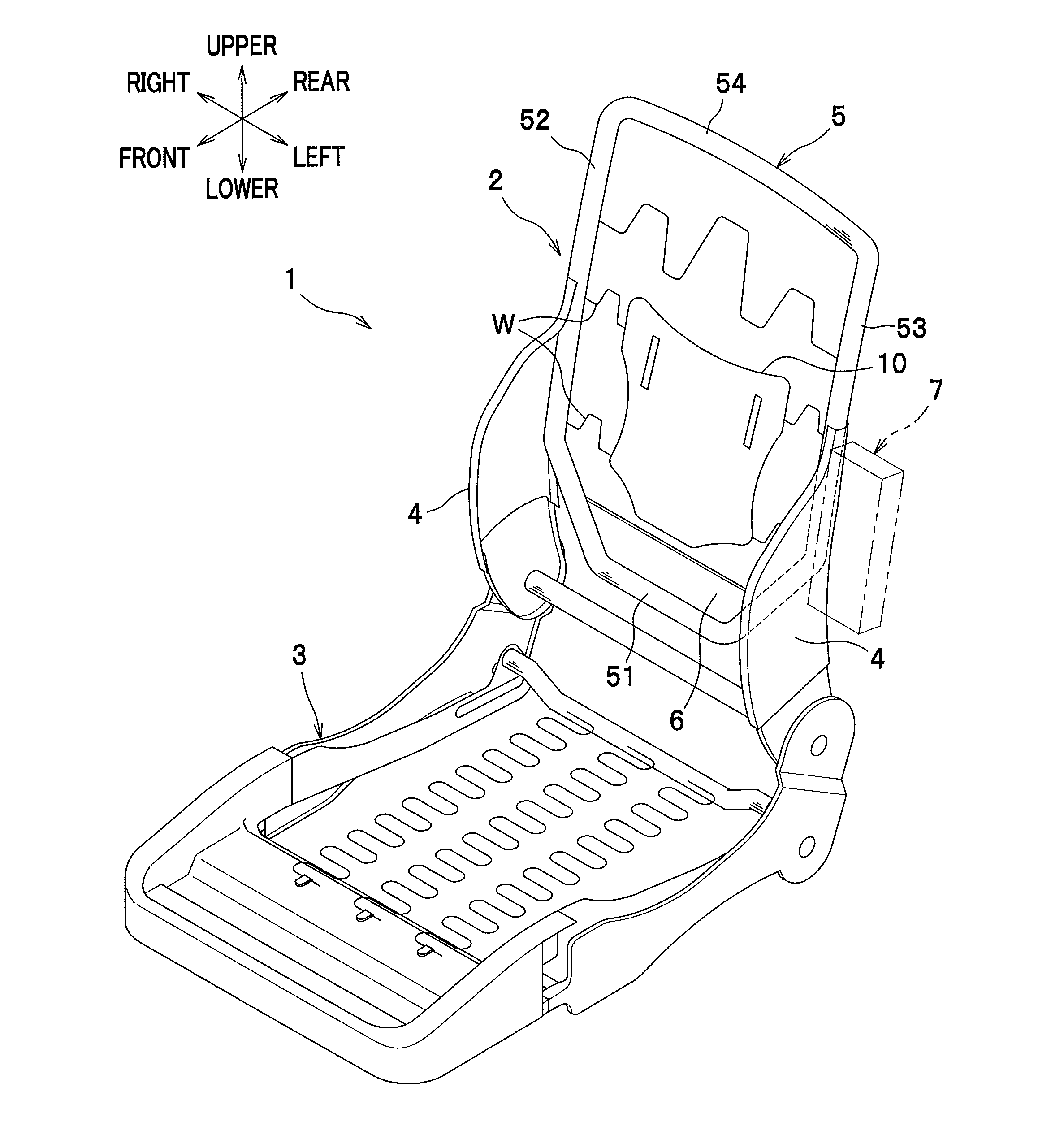
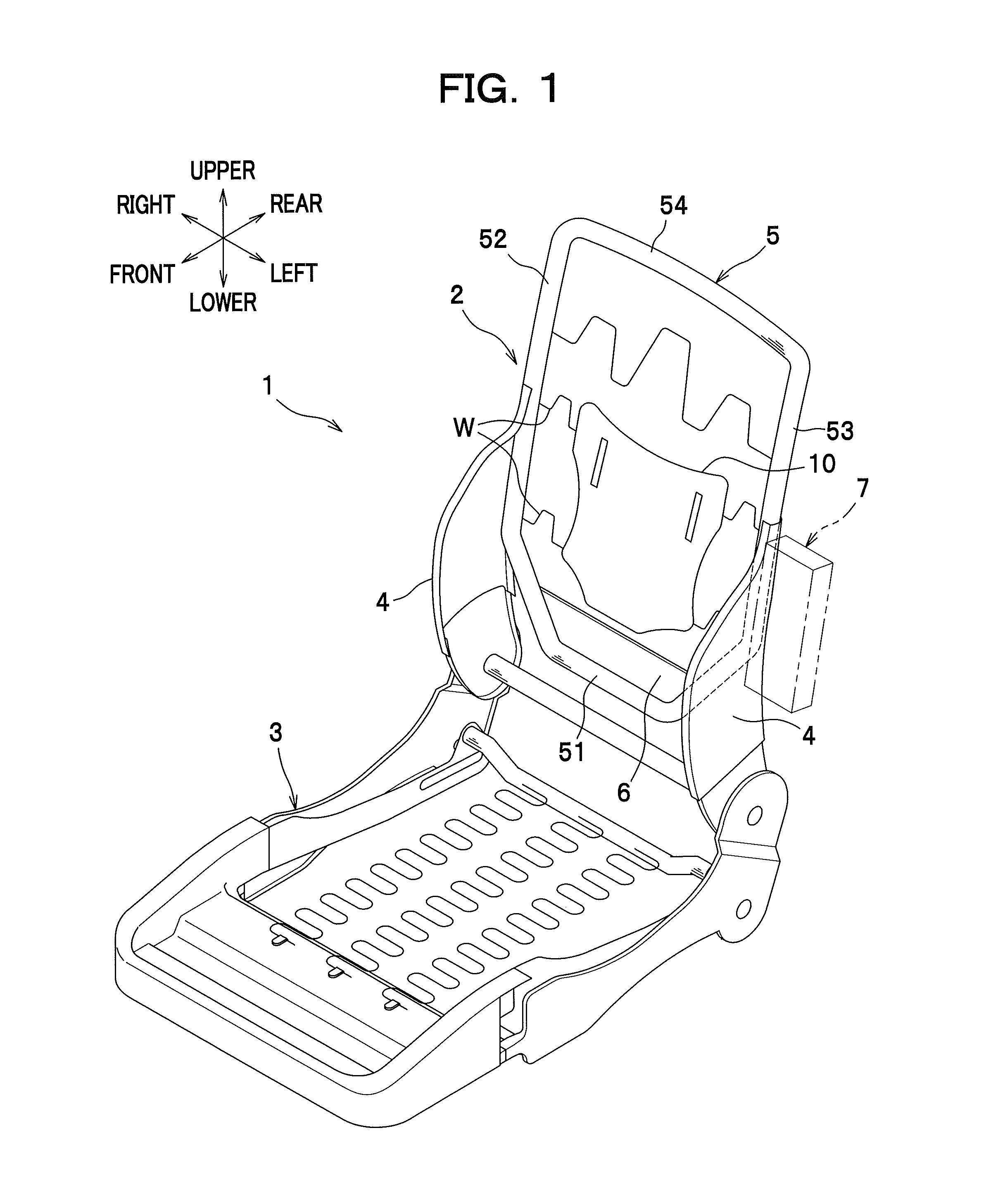
[0022]A vehicle seat according to the present invention is made up of a seat frame 1 as shown in FIG. 1 the outside of which is covered with a seat cushion made of urethane foam or the like. The seat frame 1 includes a seat back frame 2 and a seat bottom frame 3. It is to be understood that in describing the present invention, the front / rear, left / right and upper / lower are defined as viewed from an occupant sitting on the seat.

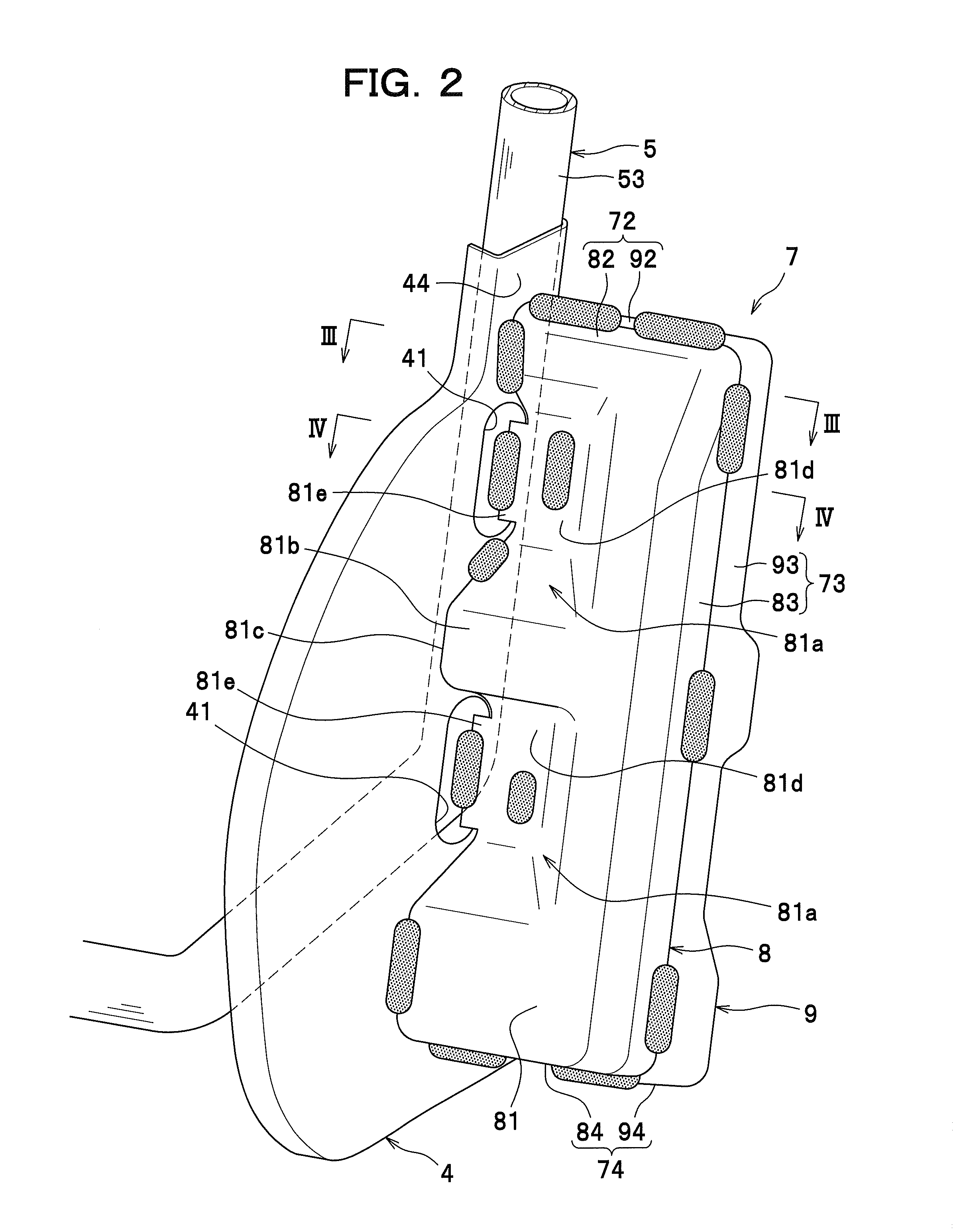
[0023]The seat back frame 2 is configured to include a pair of side frames 4, a reinforcing frame for reinforcing the side frames 4, that is, a pipe frame 5, a lower frame 6, a bracket 7 as one example of a force-receiving member, and a pressure-receiving member 10.

[0024]The pipe frame 5 has a shape of a cylindrical pipe (with a closed section), and formed by bending in the shape of a substantially rectangular loop. This pipe frame 5 comprises...


PUM


Abstract

A vehicle seat comprises: left and right base frames (side portions 52, 53 of pipe frame 5) which extend in an upward-and-downward direction and constitute left and right portions of a seat back frame (2); a pressure-receiving member (10) disposed between the left and right base frames, and configured to move rearward upon receipt of a rearward load of a predetermined magnitude or greater from an occupant; a force-receiving member (bracket 7) disposed adjacent to a left or right outer side of one base frame (side portion 53), and configured to receive a load from outside in a lateral direction; and a load transmission part (lower portion 51 of pipe frame 5) disposed under the pressure-receiving member (10), connected to a lower end of the one base frame, and configured to transmit the load from the force-receiving member to a side laterally opposite to that on which the force-receiving member is provided. The force-receiving member is provided such that the lower end of the one base frame (53) is located within a width in the upward-and-downward direction of the force-receiving member.

Description

TECHNICAL FIELD[0001]The present invention relates to a vehicle seat in which a side collision load on a vehicle can be transmitted laterally from outside toward inside.BACKGROUND ART[0002]A vehicle seat comprising: a pair of side frames which constitute left and right portions of a seat back frame; a projecting portion (force-receiving member) provided on an upper portion of an outer surface of a laterally outside side frame; and a diagonal brace disposed to extend diagonally from an upper portion of an inner surface of the laterally outside side frame to a lower portion of the inner surface of an opposite side frame to join the side frames has hitherto been known in the art (see JP 2007-326441 A).[0003]In the vehicle seat as mentioned above, a side collision load imposed to the projecting portion from outside in a lateral direction is transmitted to a side opposite to that on which the projecting portion is provided, through the laterally outside side frame, the diagonal brace and...

Claims


Application Information

Patent Timeline
Patent Type & Authority Applications(United States)
IPC IPC(8): B60N2/42
CPCB60N2/4235B60N2/42B60N2/68B60N2/42709B60N2/682B60N2/4249
Inventor KAKU, HIROYUKIYAMAKI, JOGENOKU, HISATO
Owner TS TECH CO LTD
Features
  • Generate Ideas
  • Intellectual Property
  • Life Sciences
  • Materials
  • Tech Scout
  • Unparalleled Data Quality
  • Higher Quality Content
  • 60% Fewer Hallucinations
Learn More