Positioning device adapted for positioning a detachable module in a housing

Inactive Publication Date: 2008-01-24
UNIVERSAL SCI IND CO LTD
4 Cites 15 Cited by

AI-Extracted Technical Summary

Problems solved by technology

Furthermore, the screw fasteners have a relatively small size so that the screw fasteners detached from the computer ho...

Benefits of technology

[0010]During assembly of the detachable module to the housing, initially, the positioning rods of the pivot blocks of the pivot member are guided respectively by the first slot portions of the guiding slots in the guiding members to move rearwardly as a result of rearward movement of the detachable module until the positioning rods of the pivot blocks of the pivot member abut respectively against the rear stop walls of the guiding me...

Abstract

A positioning device includes two guiding members fixed spacedly in a housing. Each guiding member has a hook-shaped guiding slot having an elongate first slot portion, and a curved second slot portion defined by front and rear stop walls. A pivot member is connected pivotally to a detachable module. Two positioning rods of the pivot member are respectively guided by the first slot portions of the guiding slots in the guiding members to move rearwardly as a result of rearward movement of the detachable module until the positioning rods abut respectively against the rear stop walls. The pivot member is then pivoted to move the positioning rods to abut respectively against the front stop walls, thereby resulting in further rearward movement of the detachable module by a predetermined distance in response to continuous pivoting of the pivot member.

Application Domain

Apparatus modification to store record carriersUndesired vibrations/sounds insulation/absorption +5

Technology Topic

EngineeringMechanical engineering

Image

  • Positioning device adapted for positioning a detachable module in a housing
  • Positioning device adapted for positioning a detachable module in a housing
  • Positioning device adapted for positioning a detachable module in a housing

Examples

  • Experimental program(1)

Example

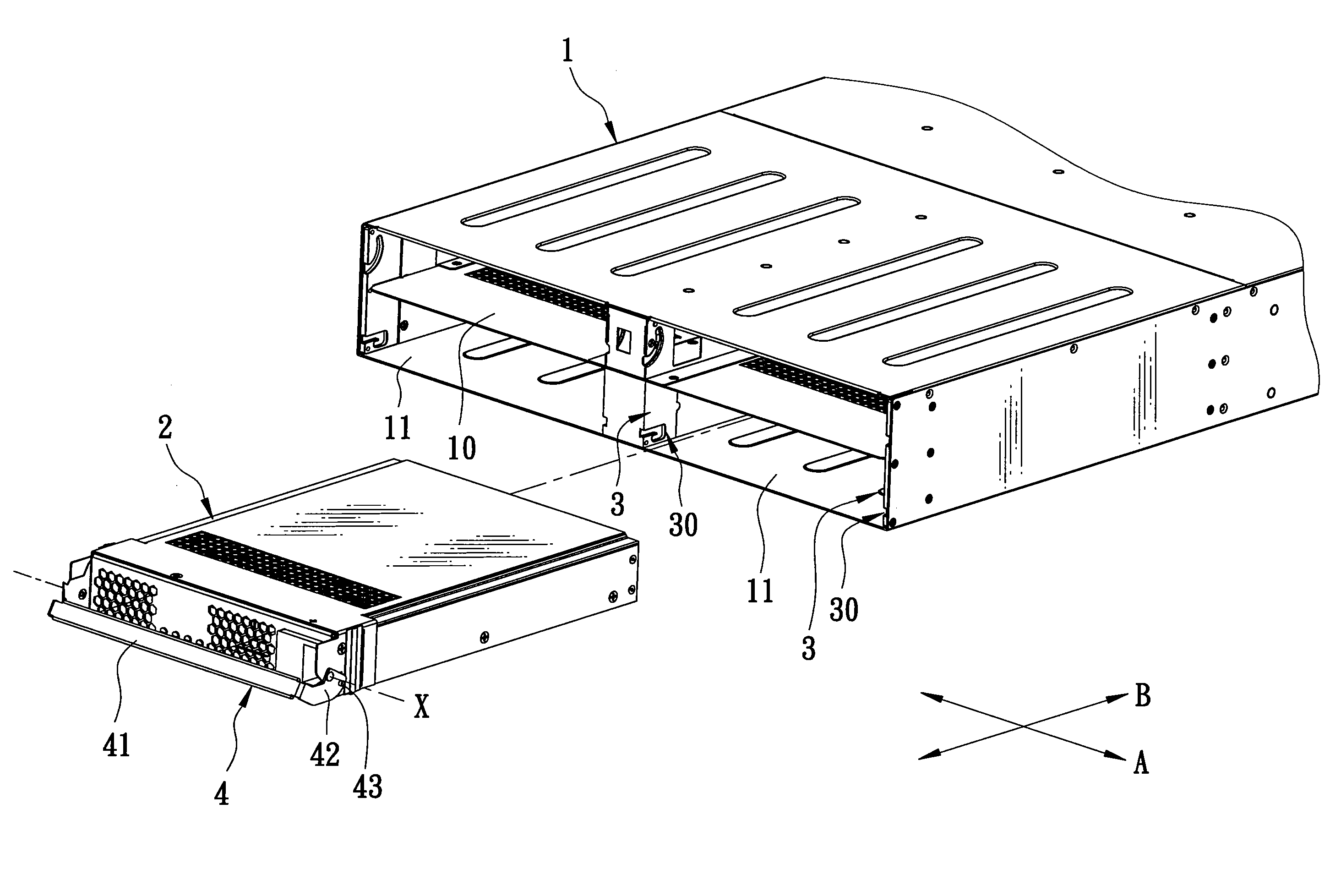
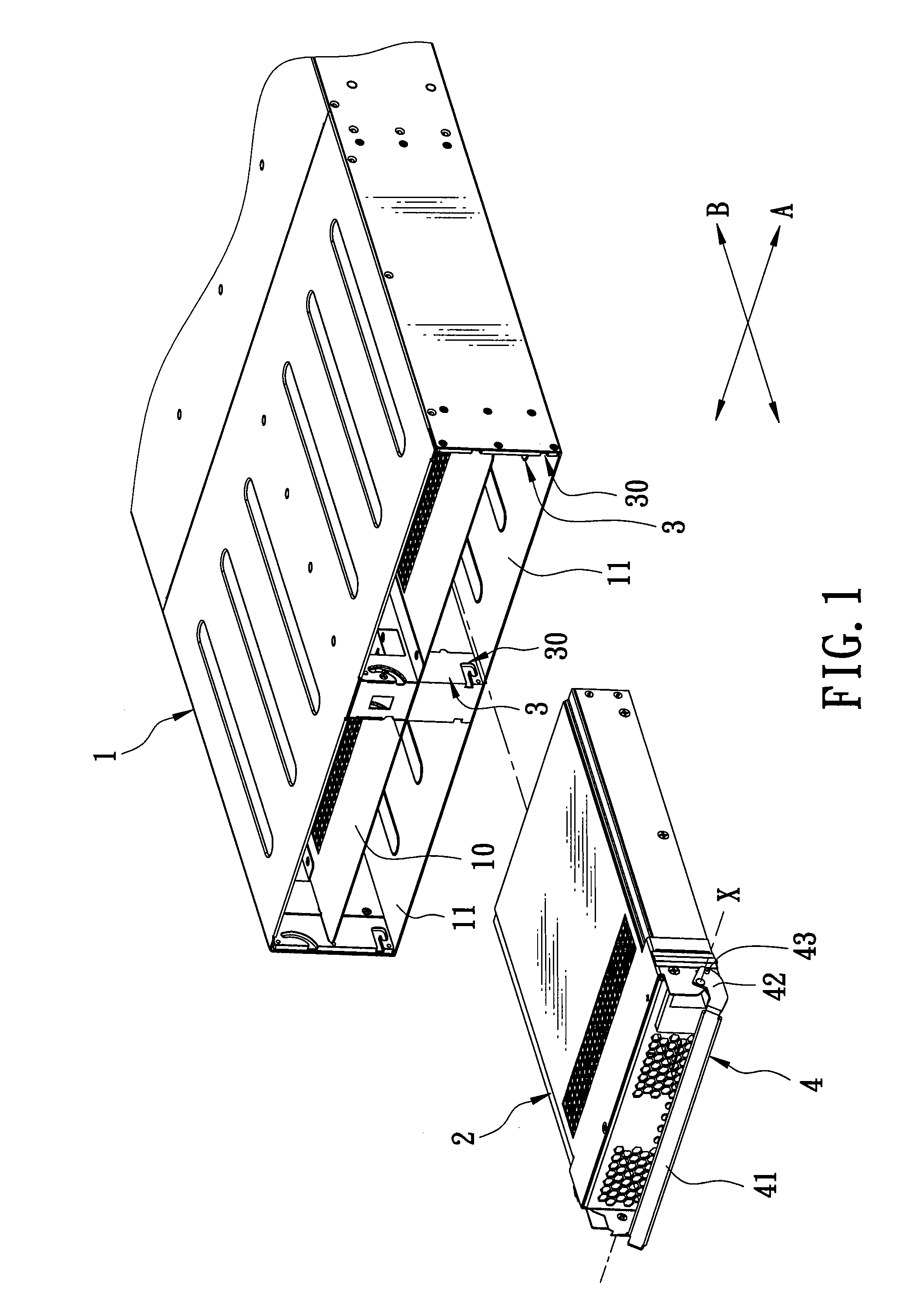
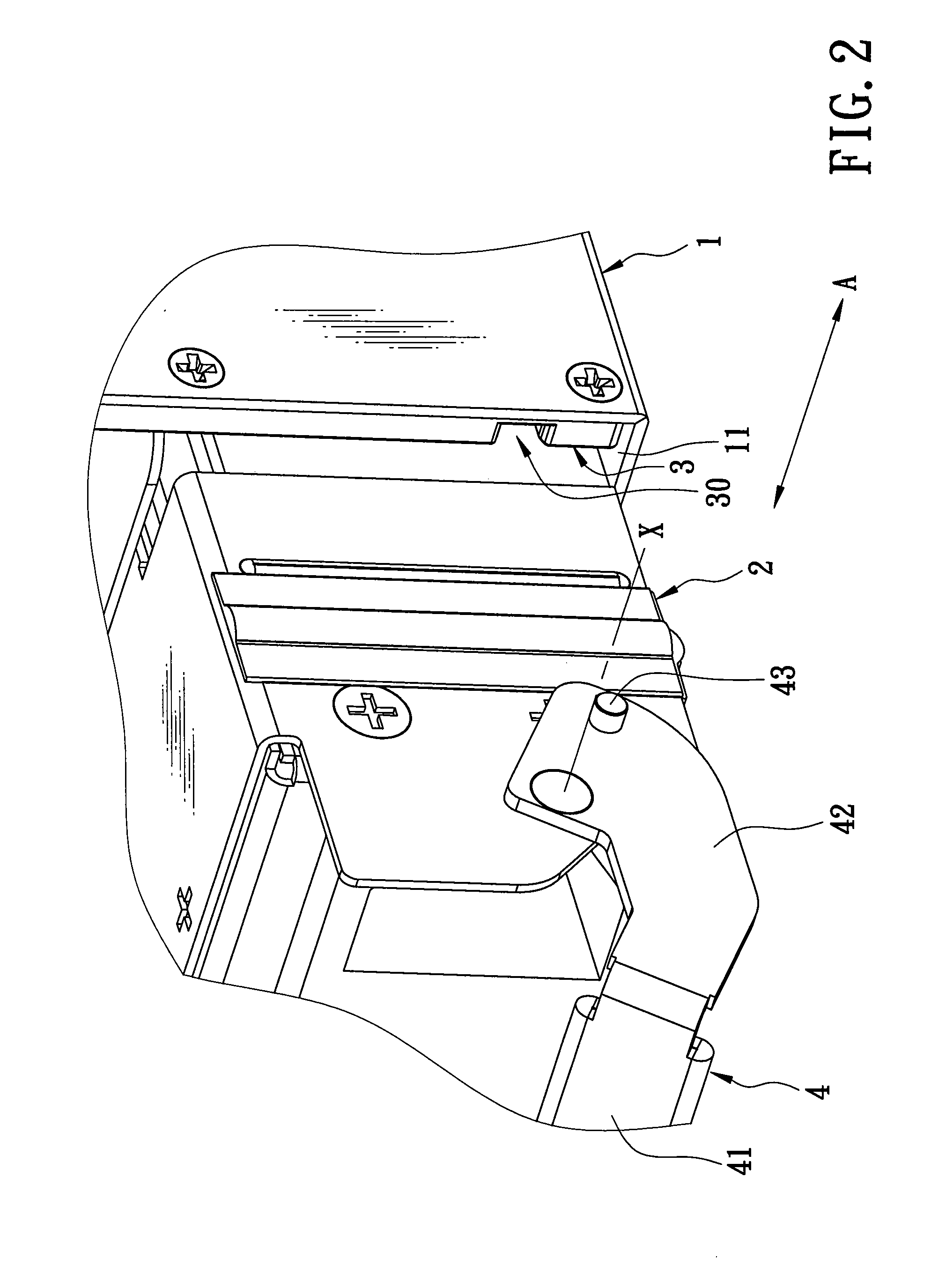
[0016]Referring to FIGS. 1 to 3, the preferred embodiment of a positioning device according to the present invention is shown to be adapted for positioning a detachable module 2 in a housing 1. In this embodiment, the housing 1 has a front open side 10, and is configured with four insertion grooves 11. The housing 1 further has four connecting ports 12 (only one is shown in FIG. 3) disposed adjacent to a rear side thereof and corresponding respectively to the insertion grooves 11. The detachable module 2 has a connector 21. When the detachable module 2 is positioned in a selected one of the insertion grooves 11 in the housing 1, the connector 21 of the detachable module 2 is connected electrically to a corresponding one of the connecting ports 12. The positioning device includes a pair of guiding members 3 and a pivot member 4.
[0017]The guiding members 3 are adapted to be mounted fixedly in the housing 1, and are spaced apart from each other in a first direction (A). In this embodiment, each guiding member 3 is in the form of a plate body that can serve as a groove-defining wall for defining the selected one of the insertion grooves 11. Each guiding member 3 is formed with a hook-shaped guiding slot 30. For each guiding member 3, the guiding slot 30 has an elongate first slot portion 31 that extends rearwardly from a front end 36 of the plate body, and a curved second slot portion 34 connected to the first slot portion 31 and extending downwardly and frontwardly from a rear end of the first slot portion 31. Each guiding member 3 has front and rear stop walls 32, 33 spaced apart from each other in a second direction (B) that is perpendicular to the first direction (A), and defining the second slot portion 34 of the guiding slot 30 in the corresponding one of the guiding members 3 therebetween, as shown in FIG. 3. Each guiding member 3 further has a protrusion 35 that extends rearwardly from an upper end of the front stop wall 32.
[0018]The pivot member 4 is adapted to be mounted pivotally on the detachable module 2 such that the pivot member 4 is pivotable relative to the detachable module 2 about an axis (X) parallel to the first direction (A). In this embodiment, the pivot member 4 has opposite pivot blocks 42 adapted to be connected respectively and pivotally to opposite lateral sides of the detachable module 2, and an intermediate handgrip 41 interconnecting fixedly the pivot blocks 42. Each pivot block 42 is disposed between a corresponding one of the guiding members 3 and the detachable module 2 when the detachable module 2 is inserted into the selected one of the insertion grooves 11 in the housing 1 via the front open side 10. Each pivot block 42 has an integral positioning rod 43 that extends outwardly in the first direction (A).
[0019]Referring further to FIGS. 4 to 7, during assembly of the detachable module 2 to the housing 1, after insertion of the detachable module 2 into the selected insertion groove 11 in the housing 1 via the front open side 10, initially, the positioning rods 43 of the pivot blocks 42 of the pivot member 4 are guided respectively by the first slot portions 31 of the guiding slots 30 in the guiding members 3 to move rearwardly toward the corresponding connecting port 12 as a result of continuous rearward movement of the detachable module 2 until the positioning rods 43 of the pivot blocks 42 of the pivot member 4 abut respectively against the rear stop walls 33 of the guiding member 3, as shown in FIG. 3. At the same time, the connector 21 of the detachable module 2 contacts merely but is not connected electrically to the selected connecting port 12.
[0020]Subsequently, the pivot member 4 is pivoted about the axis (X) in a clockwise direction from an initial first position (P1) to an intermediate second position (P2) so as to pivot the pivot blocks42 such that the positioning rods 43 of the pivot blocks 42 of the pivot member 4 move downwardly and frontwardly until the positioning rods 43 of the pivot blocks 42 of the pivot member 4 abut respectively against the front stop walls 32 of the guiding members 3, as shown in FIG. 5. At this time, due to the presence of the protrusion 35 of each pivot member 3, removal of each positioning rod 43 from the front stop wall 32 is prevented. Additionally, during pivoting of the pivot member 4 from the first position (P1) to the second position (P2), although the positioning rods 43 contact respectively rear end surfaces 351 of the protrusions 35 of the guiding members 3, as shown in FIG. 4, subsequent movement of the positioning rods 43 is not affected.
[0021]Thereafter, the pivot member 4 is continuously pivoted about the axis (X) in the clockwise direction from the second position (P2) to a final third position (P3). Further rearward movement of the detachable module 2 results from the continuous pivoting of the pivot member 4 from the second position (P2) to the third position (P3) since the positioning rods 43 abut respectively against the front stop walls 32 of the guiding members 3. In other words, a distance of the further rearward movement of the detachable module 2 is substantially equal to a movement distance (S) of the axis (X) from a position (XP1,2), where the pivot member 4 is in one of the first and second positions (P1, P2), to a position (XP3), where the pivot member 4 is in the third position (P3), as shown in FIG. 7. At this time, due to the further rearward movement of the detachable module 2, the connector 21 of the detachable module 2 is connected electrically to the selected connecting port 12.
[0022]Referring further to FIGS. 6, 8 and 9, during disassembly of the detachable module 2 from the housing 1, initially, the pivot member 4 is pivoted about the axis (X), which is at the position (XP3), in a counterclockwise direction from the third position (P3) to an intermediate fourth position (P4) so as to pivot the pivot blocks 42 such that positioning rod 43 of each pivot block 42 of the pivot member 4 moves upwardly and rearwardly in the second slot portion 34 of the guiding slot 30 in the corresponding guiding member 3 until the positioning rods 43 of the pivot blocks 42 of the pivot member 4 abut respectively against the rear stop walls 32 of the guiding members 3, as shown in FIG. 8.
[0023]Subsequently, the pivot member 4 is continuously pivoted about the axis (X) in the counterclockwise direction from the fourth position (P4) to the first position (P1). Hence, since the positioning rods 43 are blocked respectively by the rear stop walls 33 of the guiding members 3, the positioning rods 43 move upwardly and respectively along the rear stop walls 22 of the guiding members 3 such that the axis (X) is moved from the position (XP3) to the position (XP1,2), thereby resulting in frontward movement of the detachable module 2 that causes the connector 21 of the detachable module 2 to be disconnected from the selected connecting port 12, as shown in FIG. 9.
[0024]Thereafter, the detachable module 2 can be moved away from the housing 1 by operating the pivot member 4 to move frontwardly and respectively the positioning rods 43 along the first slot portions 31 of the guiding slots 30 in the guiding members 3.
[0025]In such a configuration, the positioning device of the present invention enables the detachable module 2 to be easily positioned in and detached from the housing 1 without the need for tools, thereby resulting in convenience during assembly and disassembly. Furthermore, the distance (S) derived from the pivot member 4 can be designed to be suitable for various housings with different specifications, thereby resulting in superior applicability.
[0026]While the present invention has been described in connection with what is considered the most practical and preferred embodiment, it is understood that this invention is not limited to the disclosed embodiment but is intended to cover various arrangements included within the spirit and scope of the broadest interpretation so as to encompass all such modifications and equivalent arrangements.

PUM

no PUM

Description & Claims & Application Information

We can also present the details of the Description, Claims and Application information to help users get a comprehensive understanding of the technical details of the patent, such as background art, summary of invention, brief description of drawings, description of embodiments, and other original content. On the other hand, users can also determine the specific scope of protection of the technology through the list of claims; as well as understand the changes in the life cycle of the technology with the presentation of the patent timeline. Login to view more.
Why Eureka
Try Eureka