Bucket thumb assembly

a thumb and thumb technology, applied in the field of thumb assemblies, can solve the problems of not providing a visual indication, the bracket and the attachment point are difficult, and the thumb design is complicated and expensive, and the thumb design is not good enough to provide a visual indication

Active Publication Date: 2013-05-23
CATERPILLAR INC
View PDF4 Cites 7 Cited by
  • Summary
  • Abstract
  • Description
  • Claims
  • Application Information

AI Technical Summary

Benefits of technology

The present disclosure is about a bucket thumb assembly that can be attached to a lifting arm of a machine such as an excavator or a backhoe loader. The assembly includes a mounting lug, a thumb member, a link member, and a mounting plate. The link member has one end attached to the thumb member, while the other end has an indicator block. The mounting plate has a catch and a second aperture. The assembly is designed so that the indicator block and catch work together to indicate the position of the thumb member. This allows the operator to adjust the position of the thumb member to improve the machine's performance. The technical effect of this invention is to provide an improved and efficient mechanism for positioning the thumb member of a machine.

Problems solved by technology

Proper alignment of these holes on the link, the bracket, and the attachment point is difficult because thumb assemblies and links can exceed several hundred of pounds.
While the T-shaped end and the slot will support the weight of the strut and thumb when the pin is removed to aid in connecting the strut to the bracket, the thumb assembly disclosed in the '267 patent adds significant complexity and cost to the thumb design.
Additionally, the thumb assembly disclosed in the '267 patent does not provide a visual indication when the holes in the strut and bracket are sufficiently aligned to insert the connecting pins.
This adds time, difficulty, and cost to connecting and adjusting the thumb assembly.

Method used


Image

  • Bucket thumb assembly
  • Bucket thumb assembly
  • Bucket thumb assembly

Examples


Embodiment Construction

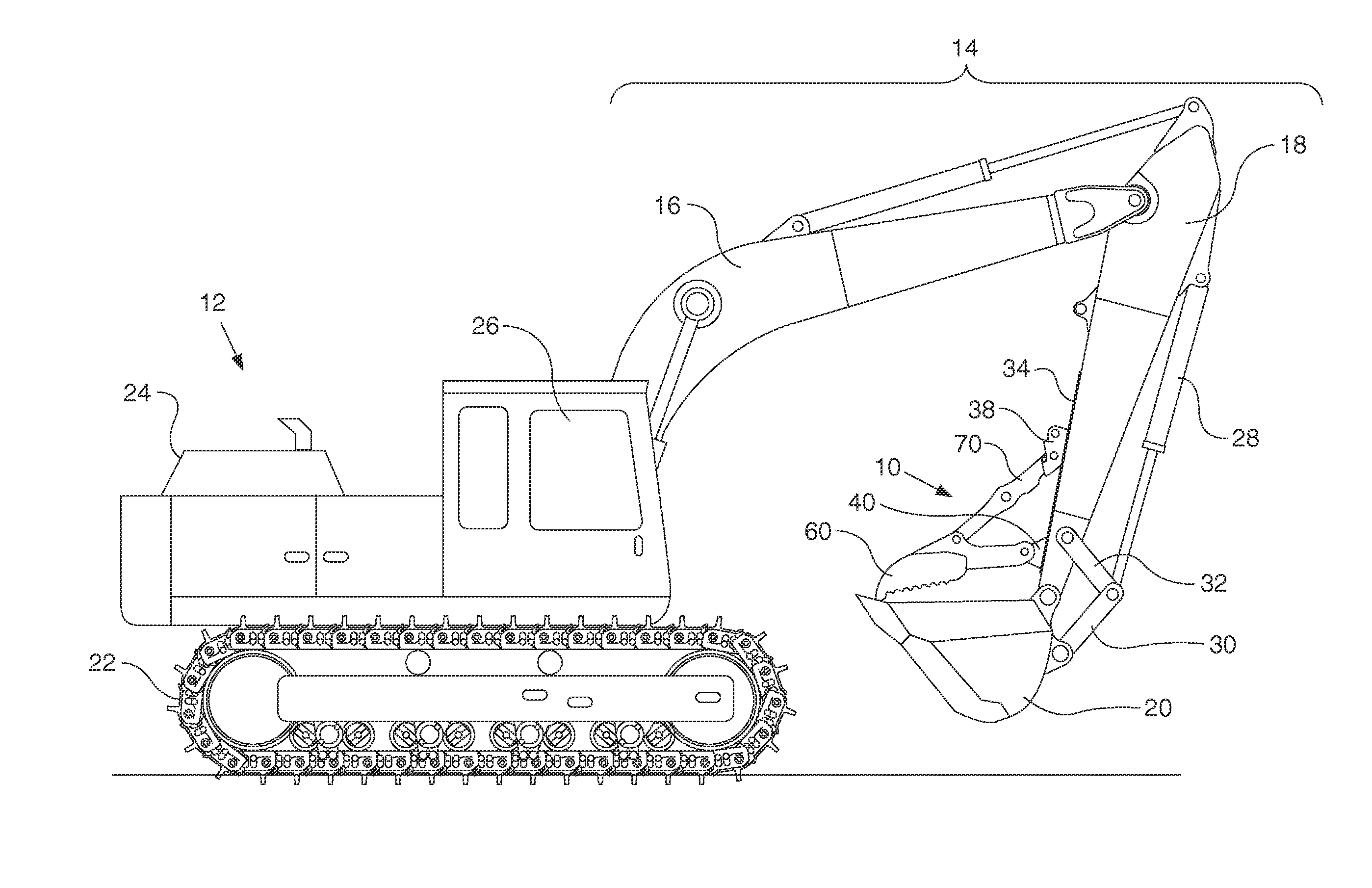
[0025]The present disclosure relates generally to a thumb assembly configured for use with a bucket on a machine, such as a material-handling machine. More specifically, the present disclosure relates to a bucket thumb assembly having a connection assist system with a connecting pin alignment indicator. While embodiments discussed herein and shown throughout the figures relate to a thumb assembly coupled to an excavator machine, it should be readily understood by those having ordinary skill in the art that embodiments of the present disclosure might be easily coupled to and used with other types of machines.

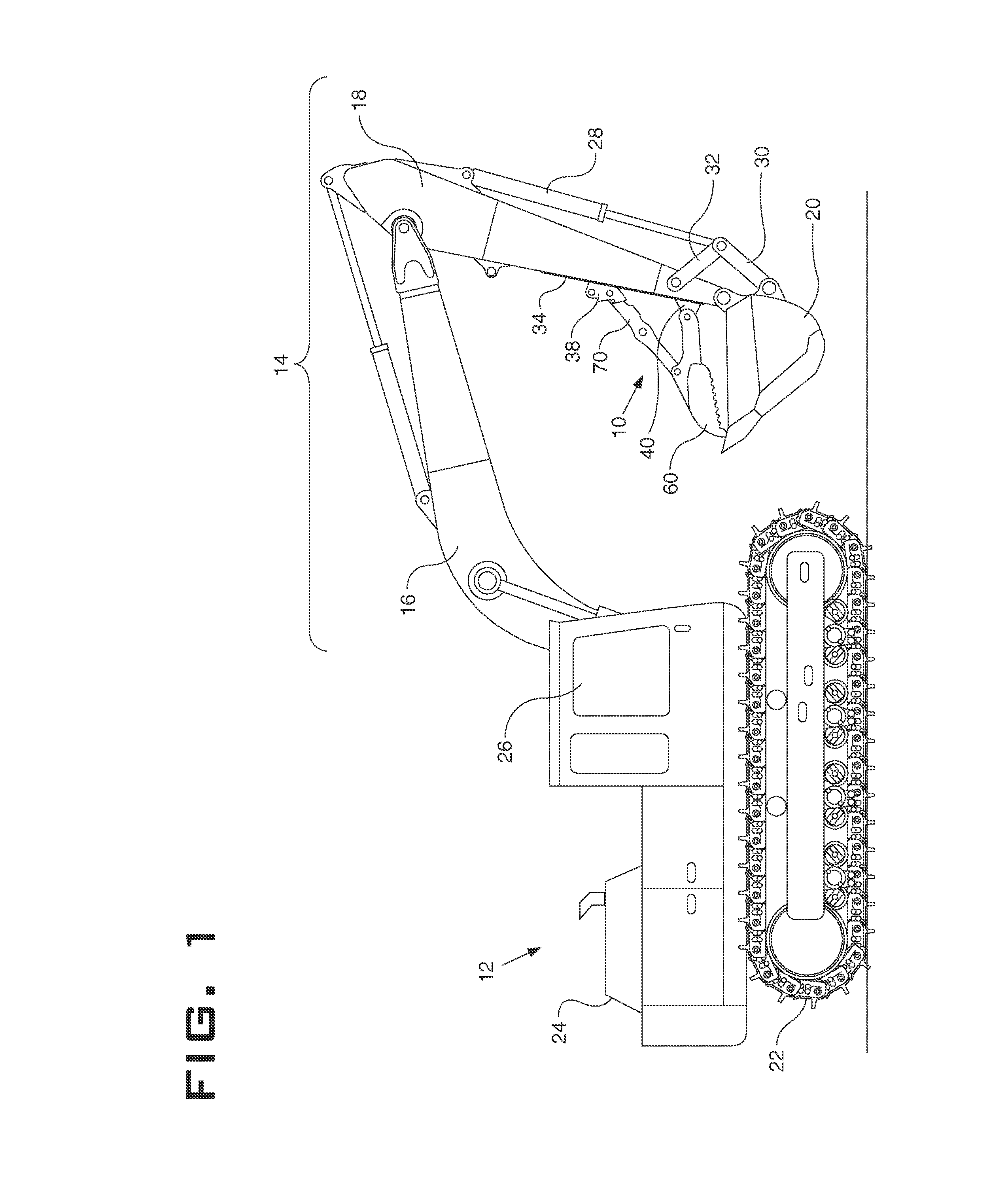
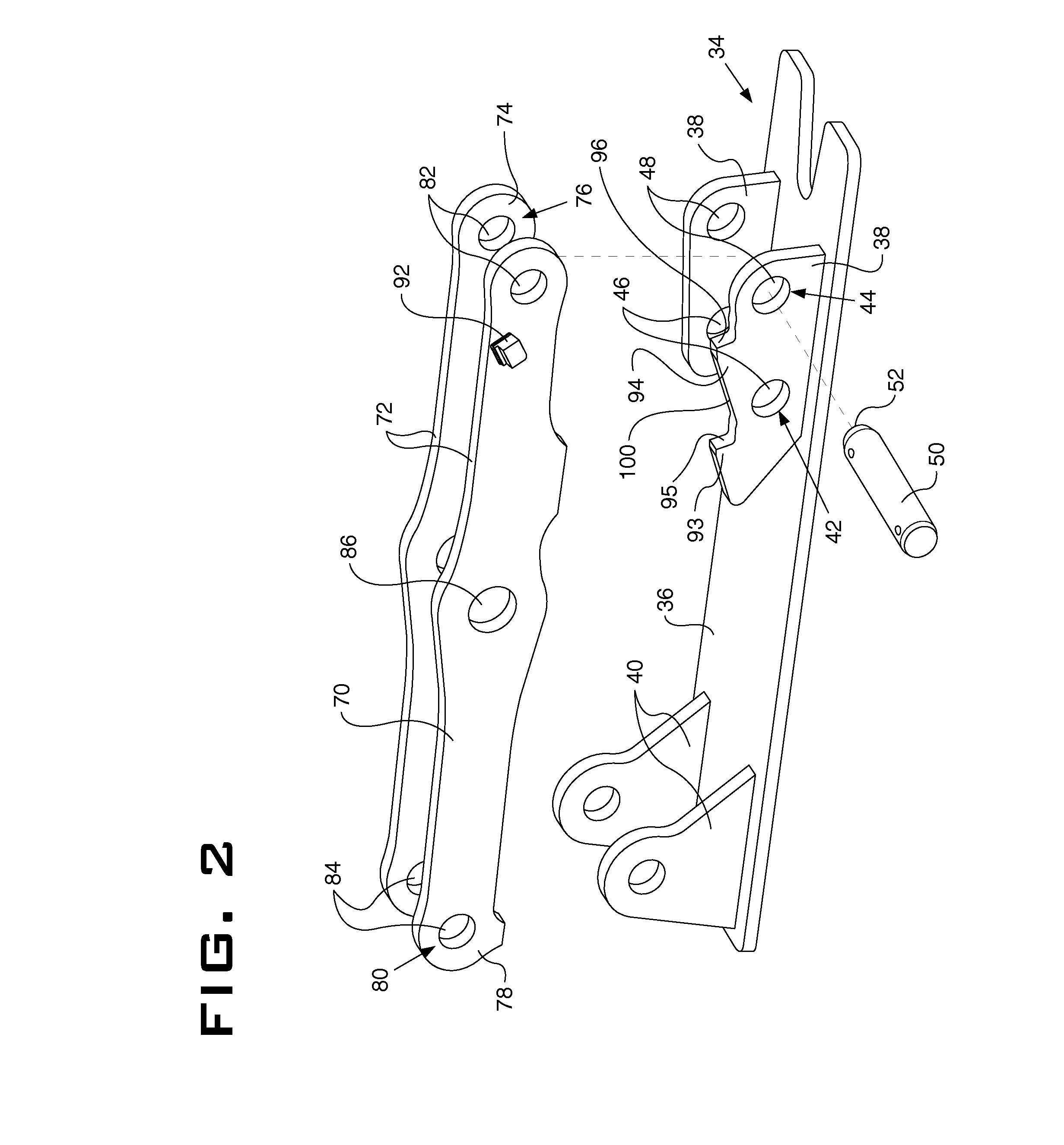
[0026]FIG. 1 illustrates a side view of a machine (e.g., an excavator) 12 provided with an embodiment of a bucket thumb assembly 10 having a connection assist system with a connecting pin alignment indicator. FIGS. 2-9A illustrate various views of embodiments of the thumb assembly 10 and the connecting pin alignment indicator system.

[0027]The Machine 12 may embody a fixed or mobi...


PUM


Abstract

A bucket thumb assembly mountable to a lifting arm of a machine (e.g., an excavator or a backhoe loader) includes a mounting lug and a thumb member pivotably coupled to the mounting lug. The bucket thumb assembly also includes a link member extending from the thumb member. The link member has a first aperture at a first end of the link member. The link member has an indicator block extending from the link member. The bucket thumb assembly further includes a mounting plate having a second aperture and a catch. The mounting plate is configured to selectively couple with the link member using a pin inserted through the first and second apertures when the indicator block is resting on the catch such that a face surface on the indicator block and a face surface of the catch are substantially co-planar.

Description

TECHNICAL FIELD[0001]The present disclosure relates generally to a thumb assembly used with a pivoting bucket on a machine, such as an excavator. More specifically, the present disclosure relates to a bucket thumb assembly having a visual connection assist system with a connecting pin alignment indicator.BACKGROUND[0002]A bucket thumb is generally understood in the industry as an implement, which is mounted on an underside of a stick on an excavator boom. The thumb generally opposes the excavator bucket for grasping material held between the bucket and the thumb. There are two main types of bucket thumbs, stiff link thumbs and hydraulically actuated thumbs. Stiff link thumbs are fixed or rigidly orientated relative to the stick and / or the bucket. Conversely, hydraulically actuated thumbs pivot or otherwise move relative to the stick and / or the bucket using a hydraulic cylinder actuated by hydraulic force. In use, the bucket is rotated relative to the stick to grasp and hold material...

Claims


Application Information

Patent Timeline
IPC IPC(8): E02F3/413
CPCE02F9/26E02F3/404E02F3/413
Inventor SELJESTAD, GREGORY A.
Owner CATERPILLAR INC
Why Eureka
Try Eureka