Adjustable electrical busway joint

Active Publication Date: 2013-07-04
ABB (SCHWEIZ) AG
View PDF0 Cites 18 Cited by
  • Summary
  • Abstract
  • Description
  • Claims
  • Application Information

AI Technical Summary

Problems solved by technology

As a result, two custom length busway joint elbows need to be manufactured, adding significant cost and time to the installation.
Fo

Method used


Image

  • Adjustable electrical busway joint
  • Adjustable electrical busway joint
  • Adjustable electrical busway joint

Examples


Embodiment Construction

[0027]As used in this description and in the claims which follow, the term “phase” shall be taken to include all conductors in different runs of any particular busway, bus duct, or bus joint which carry the same electrical phase, and including those conductors which are used to carry any neutral or ground phase.

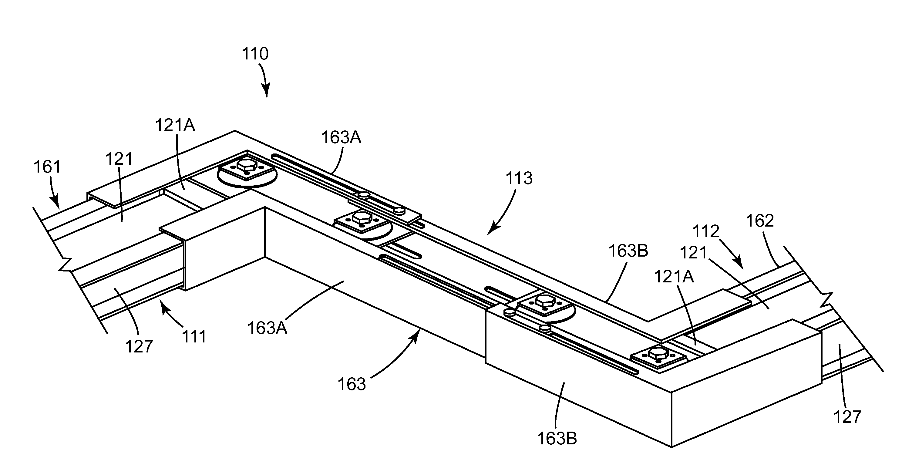
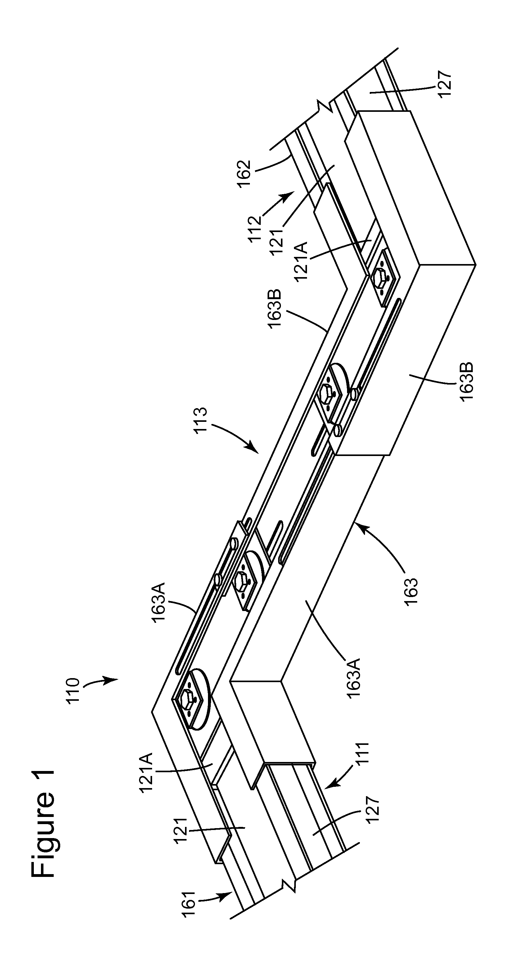
[0028]Various embodiments disclosed herein provide a busway joint which is adjustable by a user to any desired length. Embodiments use a splice-plate style pressure joint to couple two longitudinally offset busway sections. The splice plates comprising the joint are longitudinally moveable with respect to each other between a first compressed position and a second extended position such that the busway joint length is likewise adjustable.

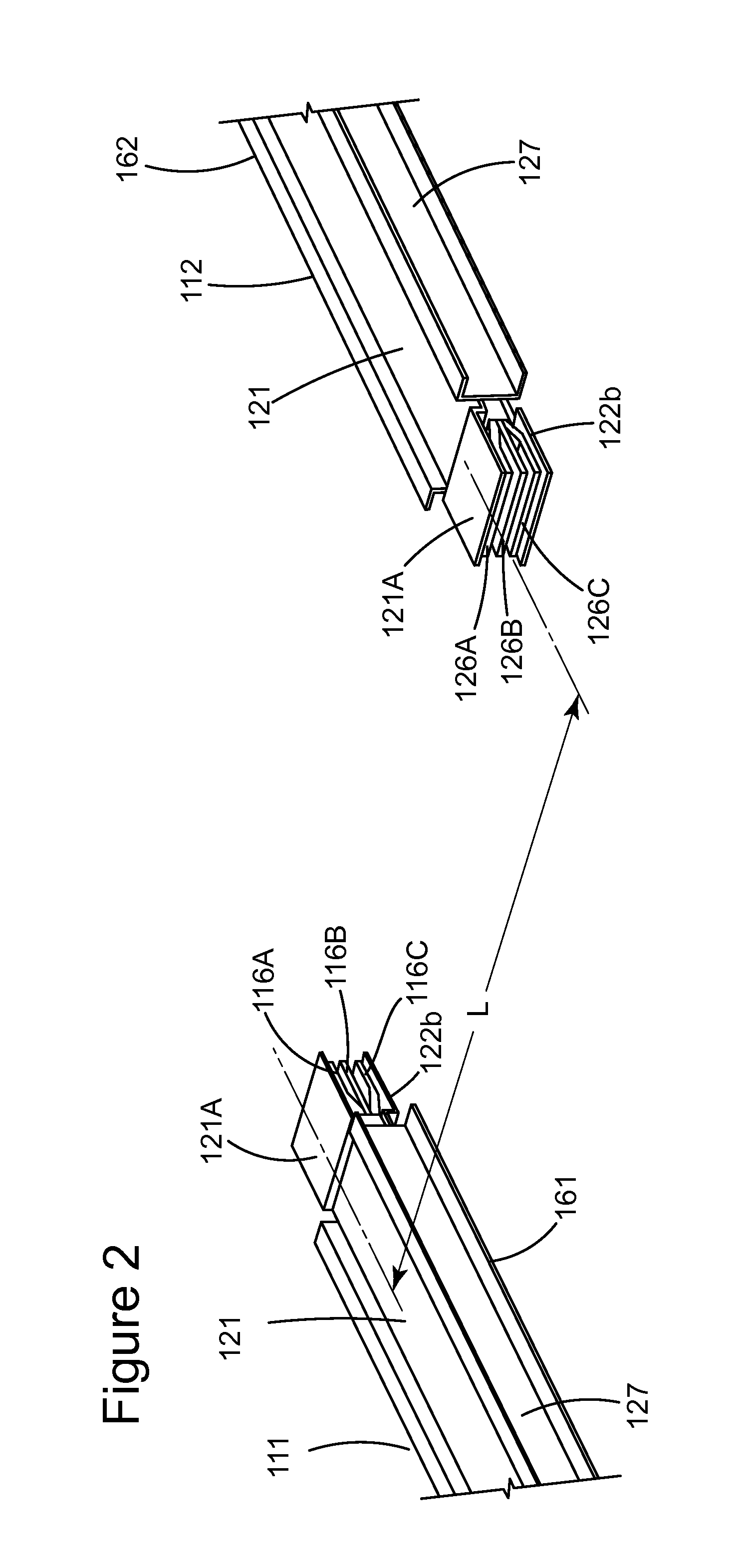
[0029]Exemplary embodiments comprise a first set of splice plates, each respectively defining a first splice plate first retaining portion, and a second set of splice plates each respectively defining a second aperture arranged to define a fi...


PUM


Abstract

An adjustable length busway joint for coupling a first and a second busway section, the first and second busway sections being longitudinally offset, is disclosed. The busway joint includes a first plurality of splice plates and a second plurality of splice plates disposed to overlap to form an electrical joint. The first and said second pluralities of splice plates are arranged for a longitudinal movement with respect each other between a first compressed position and a second extended position. The busway joint further includes a third plurality of splice plates. Each splice plate of the second plurality of splice plates overlaps a portion of a corresponding splice plate of the third plurality of splice plates to form an electrical joint. The third and second pluralities of splice plates are arranged for a longitudinal movement with respect each other between a third compressed position and a fourth extended position.

Description

BACKGROUND OF THE INVENTION[0001]The embodiments described herein relate generally to electrical busway and, more particularly, to an adjustable joint for joining electrical busway sections.[0002]Elongated rectangular flat conductive bus bar members are conventionally insulatively arranged within electrical busway sections for transporting multi-phase high current electric power through industrial establishments. Successive elongate busway sections are electrically connected or interlocked together in end-to-end relation to provide electrical continuity between a power source and a power consuming load.[0003]When offset or non-longitudinally aligned busway sections are electrically interconnected in a conventional installation, one or more self-contained busway joint is typically employed. In order to preserve the thermal properties of the individual busway sections, the busway joint is conventionally constructed with electrically conductive splice plates and interleaving insulative...

Claims


Application Information

Patent Timeline
IPC IPC(8): H01R4/60
CPCH02G5/007
Inventor MOONEY, BRIAN FREDERICKWOOD, MICHAEL RICHARDCOX, JEFFERY LYNNWITKOSKI, GERALDDUDA, MARIUSZSCHATZ, MARKBHATHIJA, KULDEEP KUMAR
Owner ABB (SCHWEIZ) AG
Why Eureka
Try Eureka