
High pressure lock assembly

Active Publication Date: 2013-07-11
BAKER HUGHES INC
View PDF16 Cites 0 Cited by
  • Summary
  • Abstract
  • Description
  • Claims
  • Application Information

AI Technical Summary

Benefits of technology

The patent describes a way to lock an assembly by moving a part called an extender member relative to a mandrel with windows and struts. The extender member has dogs that fit through the windows and land on a feature called a landing. This design allows the struts to be loaded without putting pressure on them during assembly. The technical effect of this method is a more efficient and reliable way to lock assemblies.

Problems solved by technology

In order to accommodate the dogs, windows must be formed in a mandrel or other component of the tubular string, with relatively narrow struts located between each window presenting likely failure points when the string experiences high pressure situations.
This results in the need to balance the width of the dogs and the width of the struts, as making either too small can result in failure of the system (e.g., inability of the dogs to lock the string in place and / or fracture of the struts due to heavy loading).

Method used


Image

  • High pressure lock assembly
  • High pressure lock assembly
  • High pressure lock assembly

Examples


Embodiment Construction

[0008]A detailed description of one or more embodiments of the disclosed apparatus and method are presented herein by way of exemplification and not limitation with reference to the Figures.

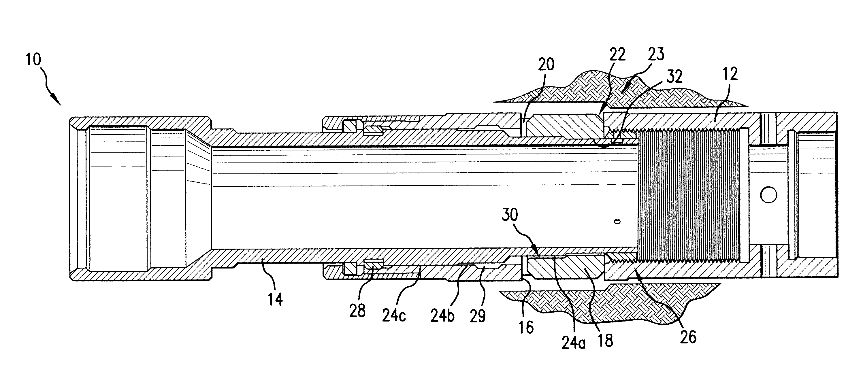
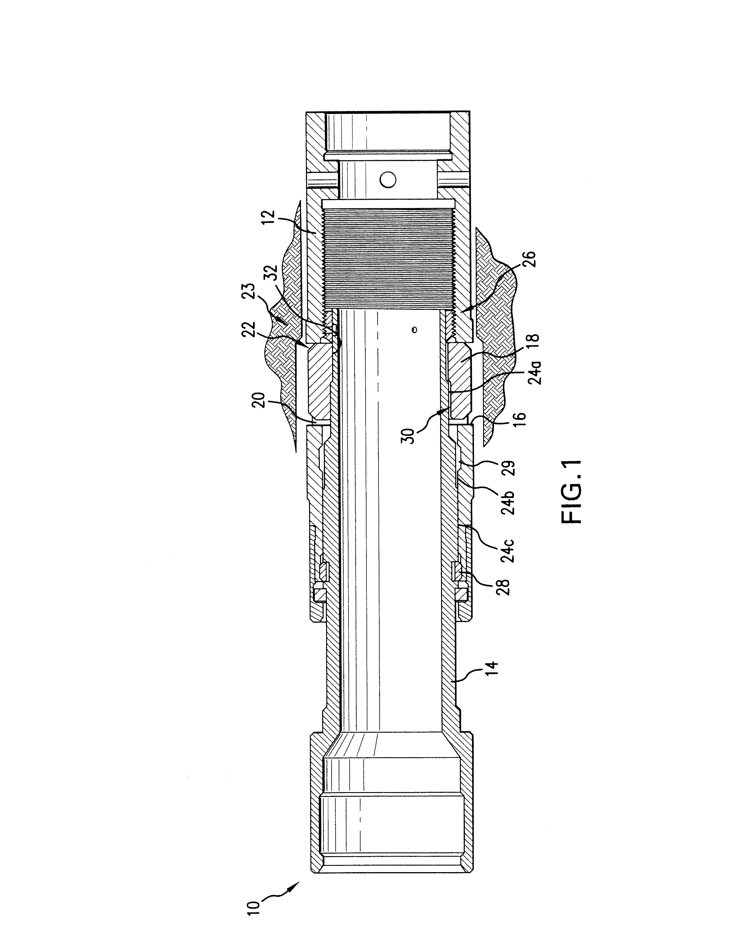
[0009]Referring now to FIG. 1, a locking assembly 10 is shown having a mandrel 12 and an extender 14. The mandrel 12 includes plurality of windows 16 for accommodating a plurality of locking dogs 18 therein, with one dog 18 in each window 16. The mandrel 12 further includes struts 20, with one strut 20 located adjacently between each pair of the windows 16. The mandrel 12 and the extender 14 are, for example, part of a tubular string runnable downhole in a borehole.

[0010]The extender 14 is arranged to radially extend dogs 18, either radially inwardly or outwardly, through respective ones of the windows 16. For example, the dogs 18 include a surface 22 that is arranged to correspondingly engage with another surface, e.g., a landing nipple, recess, radial restriction or other engagement surface in ...


PUM


Abstract

A lock assembly including a mandrel having one or more windows arranged alternatingly with one or more struts. One or more dogs are included corresponding to the one or more windows and are radially extendable therethrough. A member is operatively arranged for radially extending each of the one or more dogs. Each of the one or more dogs is operatively coupled between the member and the mandrel when fully radially extended by the member for bypassing loading in the one or more struts during loading of the assembly. A method of locking an assembly is also included.

Description

BACKGROUND[0001]Lock assemblies are ubiquitous in the downhole drilling and completions industry. One common type of lock assembly involves locking a plug, choke, pressure holding device, tool, etc., in place by radially extending a plurality of dogs into engagement with corresponding features of a radially disposed tubular. In order to accommodate the dogs, windows must be formed in a mandrel or other component of the tubular string, with relatively narrow struts located between each window presenting likely failure points when the string experiences high pressure situations. This results in the need to balance the width of the dogs and the width of the struts, as making either too small can result in failure of the system (e.g., inability of the dogs to lock the string in place and / or fracture of the struts due to heavy loading). In view of these issues and the prevalence of dog type locking systems in the industry, advances and alternatives in the field of lock assemblies are alw...

Claims


Application Information

Patent Timeline
IPC IPC(8): E21B23/02
CPCE21B23/02
Inventor MURRAY, DOUGLAS J.
Owner BAKER HUGHES INC
Learn More