Battery and method of use

a battery and circuit technology, applied in the field of batteries and battery circuits, can solve the problems of increasing the cost of electronic devices, adding extra weight, inconvenient and cumbersome removal or replacement of batteries,

Inactive Publication Date: 2013-07-18
XGLOW
View PDF6 Cites 45 Cited by
  • Summary
  • Abstract
  • Description
  • Claims
  • Application Information

AI Technical Summary

Benefits of technology

[0009]One or more implementations of the aspect of the invention described immediately above include one or more of the following: the battery is rechargeable; the battery chemistry lithium-ion chemistry; the battery chemistry is zinc-carbon chemistry; the battery chemistry is lead-acid chemistry; the battery chemistry is alkaline chemistry; the battery is elongated and cylindrical in shape; the first positive terminal and the second positive terminal are circular, located at a geometric center of the first and second ends, and are symmetrical about a longitudinal axis of the battery, the first and second insulators are continuous circular rings, encircle the first and second positive terminals, are located between the first and second positive terminals and the first and second negative terminals, and are symmetrical about the longitudinal axis of the battery, and first and second negative terminals are continuous circular rings that concurrently encircle first and second separators and first and second positive terminal, and are symmetrical about the longitudinal axis of the battery, the first and second positive terminals, the first and second negative terminals, and first and second insulators are concentric and share the longitudinal axis as a common center; a first load connected to the first positive terminal and the first negative terminal at the first end and a second load connected to the second positive terminal and the second negative terminal at the second end; a load connected to the first positive terminal and the first negative terminal at the first end and a charger connected to the second positive terminal and the second negative terminal at the second end; a first charger connected to the first positive terminal and the first negative terminal at the first end and a second charger connected to the second positive terminal and the second negative terminal at the second end; a battery-powered ...

Problems solved by technology

Although both methods are effective, they add extra weight and increased cost in the product of the electronic devices a...

Method used


Image

  • Battery and method of use
  • Battery and method of use
  • Battery and method of use

Examples


Embodiment Construction

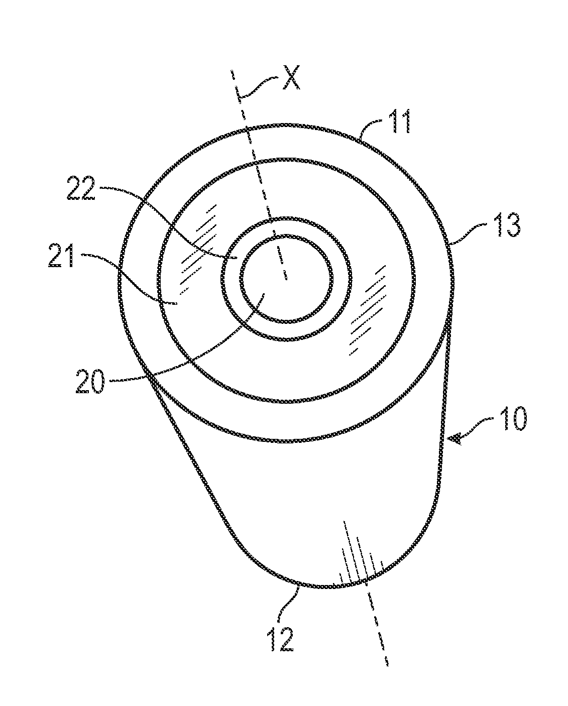
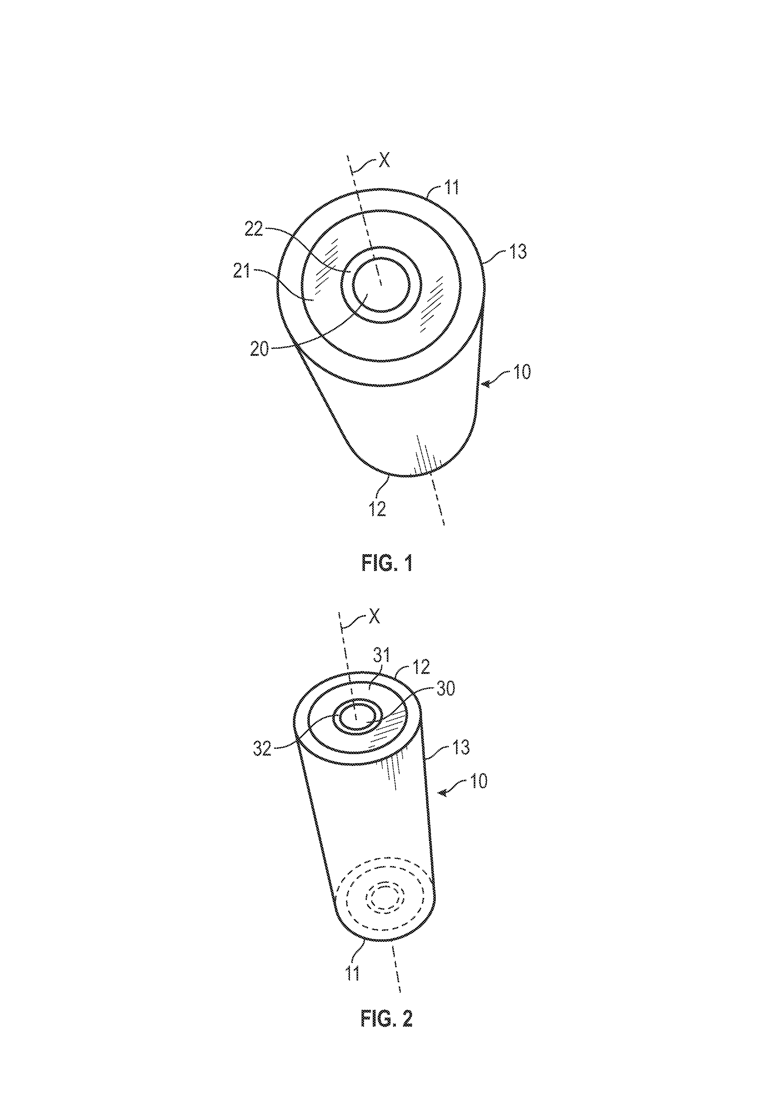
[0013]Turning now to the drawings, in which like reference characters indicate corresponding elements throughout the several views, attention is first directed to FIGS. 1 and 2 in which there is seen a battery 10 constructed and arranged in accordance with the principle of the invention. Battery 10 is elongate and cylindrical in shape, has opposed ends 11 and 12, and is symmetrical along its central, longitudinal axis X extending centrally through battery 10 from end 11 to end 12. The internal workings of battery 10 are housed within a metal or plastic case 13, which extends along the length of battery 10 from end 11 to end 12. End 11 of battery 10 as illustrated in FIG. 1 is formed with a positive terminal denoted at 20 and a negative terminal denoted at 21, and end 12 of battery 10 as shown in FIG. 2 is formed with a positive terminal denoted at 30 and a negative terminal denoted at 31. Positive and negative terminals 20 and 21 are located at end 11 of battery 10, and positive and...


PUM


Abstract

A battery includes a battery case including battery chemistry for supplying electricity, a first end, and a second end opposite the first end; a first positive terminal, a first negative terminal, and a first insulator therebetween at the first end that together form a first positive terminal and negative terminal configuration; a second positive terminal, a second negative terminal, and a second insulator therebetween at the second end that together form a second positive terminal and negative terminal configuration, wherein the second positive terminal and the second negative terminal configuration is a mirror image of the first positive terminal and the first negative terminal configuration.

Description

CROSS-REFERENCE TO RELATED APPLICATION[0001]This application claims the benefit of provisional application No. 61 / 586,196, filed on Jan. 13, 2012, which is hereby incorporated herein by reference.FIELD OF THE INVENTION[0002]The present invention relates to batteries and to battery circuits.BACKGROUND OF THE INVENTION[0003]A typical battery has two terminals. One terminal is marked (+), or positive, and the other is marked (−), or negative. In normal flashlight batteries, such as conventional AA, C or D cell batteries, the terminals are located at the opposed ends of the battery. To harness the electric charge produced by a battery, the battery must be connected to a load, such as a light bulb, a motor, or an electrical circuit.[0004]The internal workings of a battery are housed within a metal or plastic case. Inside this case are a cathode, which connects to the positive terminal, and a corresponding anode, which connects to the negative terminal. These components, which are electro...

Claims


Application Information

Patent Timeline
IPC IPC(8): H01M2/30H01M2/02F21L4/08H05K5/00H02J7/00H01M50/107H01M50/55H01M50/559
CPCF21L4/08H01M2/30H01M2/02H01M10/0525H01M10/06H01M10/24H01M10/0422H01M10/0436H01M10/058Y02E60/10Y02P70/50H01M50/559H01M50/55H01M50/107
Inventor POPPER, RICHARD S.JORGENSEN, JENSEN
Owner XGLOW
Why Eureka
Try Eureka