Waterproof electrical connector

a technology of electrical connectors and connectors, applied in the direction of coupling device connections, sport apparatus, gymnastics, etc., can solve the problems of easy damage, unsteady front side of the connector with respect to the printed circuit board, etc., and achieve the effect of preventing water from entering

Active Publication Date: 2013-07-18
HON HAI PRECISION IND CO LTD
View PDF8 Cites 100 Cited by
  • Summary
  • Abstract
  • Description
  • Claims
  • Application Information

AI Technical Summary

Benefits of technology

[0007]Accordingly, an object of the present invention is to provide an electrical connector securely fixed to a printed circuit board and effectively preventing water from entering.

Problems solved by technology

However, the connection between the electrical connector and a printed circuit board on which the electrical connector is mounted is achieved only by soldering the tail portions of the terminals to the printed circuit board, which is apt to damage.
Because the fixing legs of the metal shell and a plurality of soldering portions of the contacts are both located similarly along a straight line at a rear side of the connector, the front side of the connector is very unsteady with respect to the printed circuit board.

Method used


Image

  • Waterproof electrical connector
  • Waterproof electrical connector
  • Waterproof electrical connector

Examples


Embodiment Construction

[0015]Reference will now be made in detail to the preferred embodiment of the present invention.

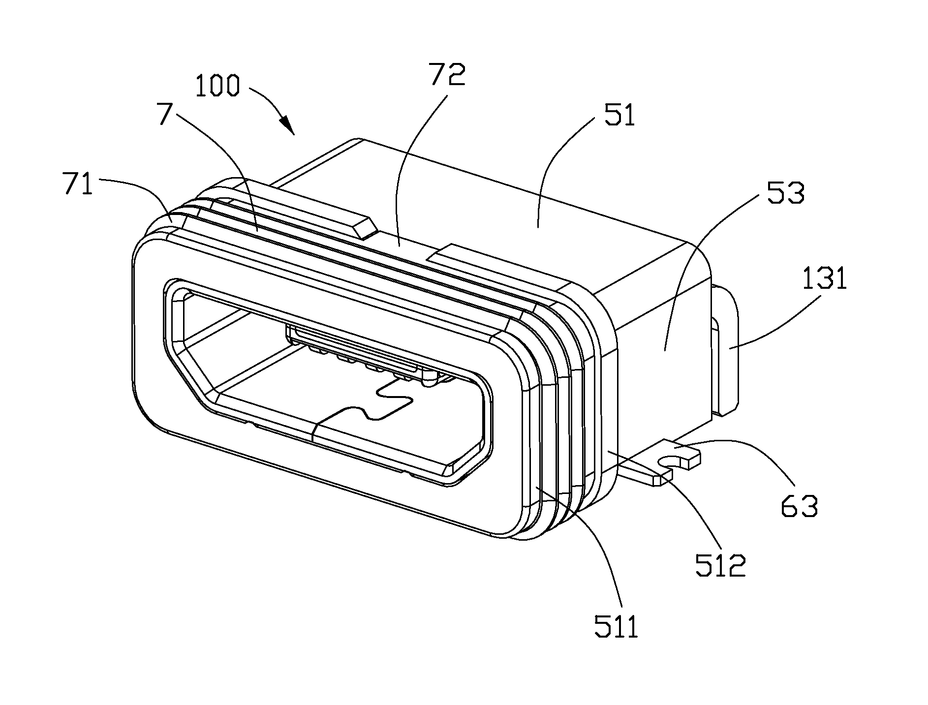
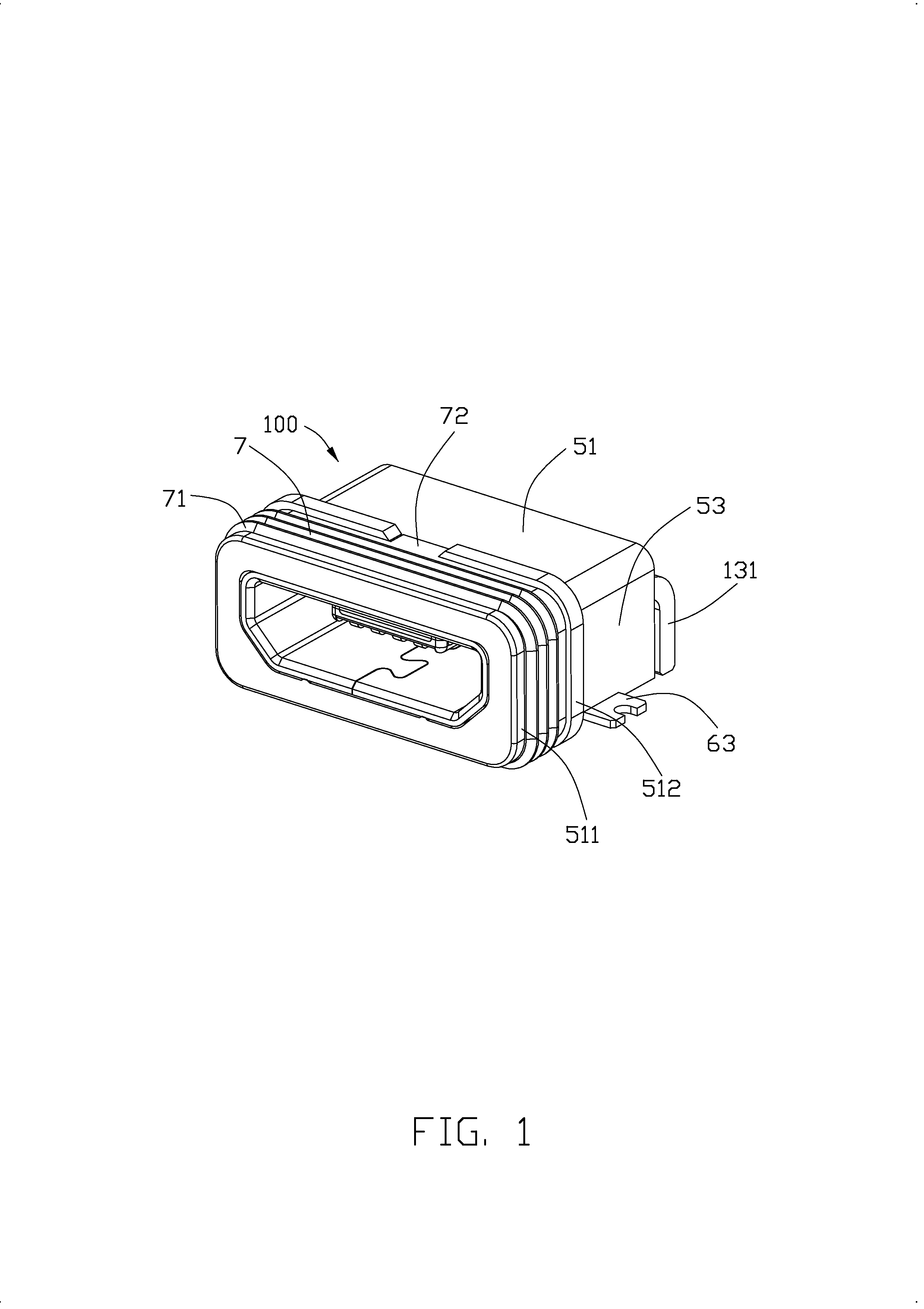
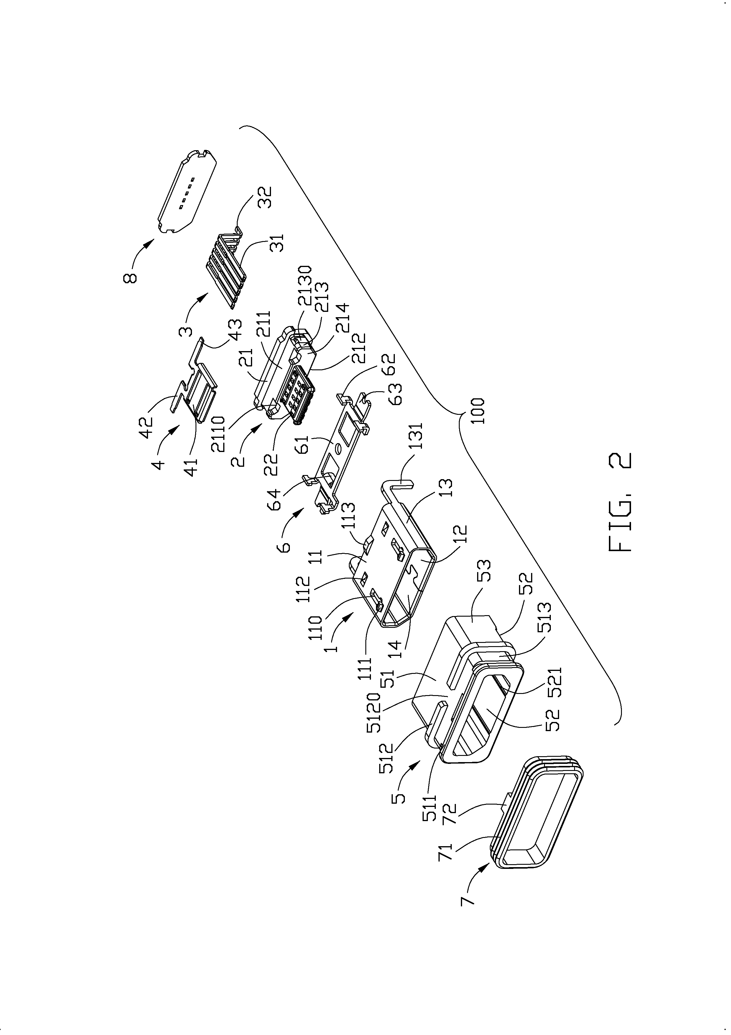
[0016]Referring to FIGS. 1 to 5, an electrical connector 100 of the present invention comprises a metallic shell 1, an insulating housing 2 combined to the metallic shell 1, a plurality of terminals 3 and a metal plate 4 retained in the insulating housing 2, an insulative cover 5 covering the metallic shell 1, a metal fixing member 6 attached to a bottom face of the insulative cover 5, a waterproof ring 7 encircling a front end of the insulative cover 5, and a waterproof plate 8, which is an epoxy coating in this embodiment, attached to a rear face of the insulative cover 5. The nouns of locality “bottom, front, rear” are not meant to be limiting but are descriptive of depiction according to the claims.

[0017]Referring to FIGS. 2 to 4, the metallic shell 1 comprises a top wall 11, a bottom wall 12, and a pair of lateral walls 13 connecting with the top wall 11 and the bottom wall 12 for co...


PUM


Abstract

An electrical connector (100) includes a metallic shell (1), an insulative housing (2) combined to the metallic shell, a plurality of terminals (3) retained in the insulative housing, an insulative cover (5) covering the metallic shell, a waterproof ring (7) and a waterproof plate (8) respectively attached to a front end and a rear face of the insulative cover, and a fixing member (6) attached to the insulative cover. The fixing member includes a rectangular portion (61), at least one corner portion (62) bending from the rectangular portion along a first vertical direction and penetrating into the insulative cover, at least one soldering pad (63) extending laterally from the rectangular portion, and at least one teared portion (64) bending from the rectangular portion towards a second vertical direction opposite to the first vertical direction.

Description

BACKGROUND OF THE INVENTION[0001]1. Field of the Invention[0002]The present invention relates generally to an electrical connector, and more particularly to a waterproof electrical connector securely fixed to a printed circuit board.[0003]2. Description of Related Arts[0004]Universal Serial Bus (USB) interfaces are widely used in various electronic devices. In recent years, a micro USB interface is introduced to meet miniaturization requirement of electronic devices. Taiwan Utility Model No. M411033 discloses an electrical connector comprising a metallic shell, an insulating housing assembled to the metallic shell, and a plurality of terminals retained in the insulating housing. The insulating housing has a base portion and a tongue portion extending forwardly from the base portion. The tongue portion has an end surface and a receiving space recessed inwardly from the end surface. Each terminal has a contacting portion which is exposed in the receiving space. The electrical connecto...

Claims


Application Information

Patent Timeline
Patent Type & Authority Applications(United States)
IPC IPC(8): H01R33/965H01R24/68
CPCH01R24/68H01R33/965H01R24/62H01R13/5219H01R12/725A63B21/02A63B23/16
Inventor WANG, FEI
Owner HON HAI PRECISION IND CO LTD
Why Eureka
Try Eureka