Sheet conveying device and image forming apparatus with the same
a conveying device and a technology of image forming apparatus, applied in the directions of transportation and packaging, thin material processing, article delivery, etc., can solve the problems of easy inconvenience and degrade stacking quality, and achieve the effect of suppressing the occurrence, simple low-cost structure and simple stacking quality of sheets
- Summary
- Abstract
- Description
- Claims
- Application Information
AI Technical Summary
Benefits of technology
Problems solved by technology
Method used
Image
Examples
first embodiment
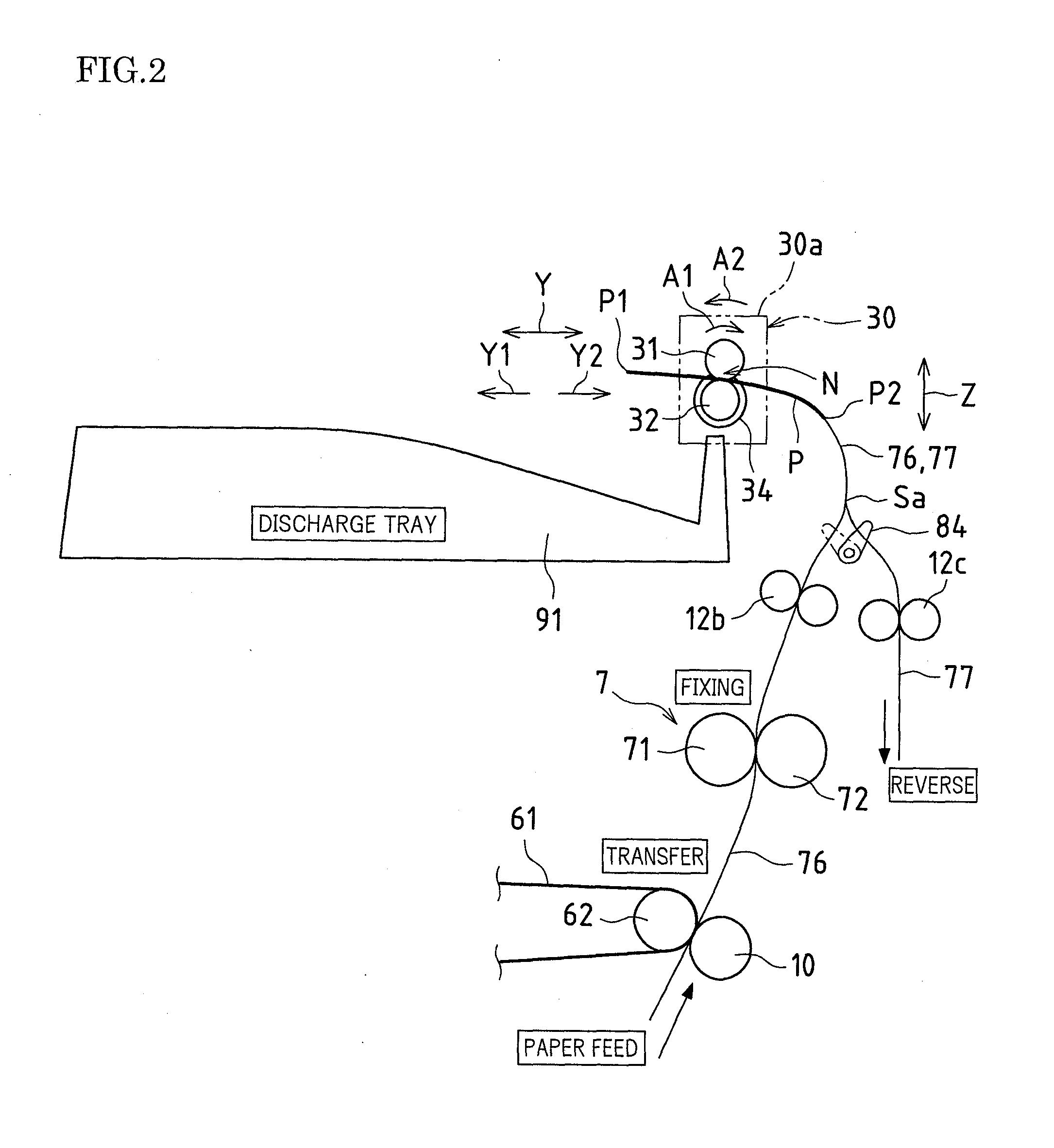
[0104]In the first embodiment, the first stiffening rollers 34a are configured to rotate integrally with the two second discharging rollers 32 at the inner side in the axial direction X. The second stiffening rollers 34b are disposed pivotally around the axis line with respect to the two second discharging rollers 32 outside in the axial direction X.
[0105]FIGS. 4A and 4B include schematic configuration views of first and second stiffening rollers 34a and 34b and their peripheral portions according to the first embodiment. FIG. 4A illustrates a schematic side view of the first stiffening roller 34a portion viewed from the conveying direction Y. FIG. 4B illustrates a schematic side view of the first stiffening roller 34a portion viewed from an axial direction X. FIG. 4C illustrates a schematic side view of the second stiffening roller 34b portion viewed from the conveying direction Y. FIG. 4D illustrates a schematic side view of the second stiffening roller 34b portion viewed from the...
second embodiment
[0112]In the second embodiment, the first stiffening rollers 34a and the second stiffening rollers 34b are each configured to integrally rotate with the second discharging rollers 32. The second stiffening rollers 34b includes a surface with a smaller friction coefficient than a friction coefficient of a surface of the first stiffening rollers 34a.
[0113]FIGS. 5A to 5D are schematic configuration diagrams of the first and second stiffening rollers 34a and 34b and their peripheral portion according to the second embodiment. FIG. 5A illustrates a schematic side view of the first stiffening roller 34a portion viewed from the conveying direction Y. FIG. 5B illustrates a schematic side view of the first stiffening roller 34a portion viewed from the axial direction X. FIG. 5C illustrates a schematic side view of the second stiffening roller 34b portion viewed from the conveying direction Y. FIG. 5D illustrates a schematic side view of the second stiffening roller 34b portion viewed from t...
embodiment
[0133]Next, the occurrence of abnormal sound in the reverse conveying path 77 was examined for each embodiment with the configuration of the first embodiment. The examination results will be described below using Comparative examples 1 and 2.
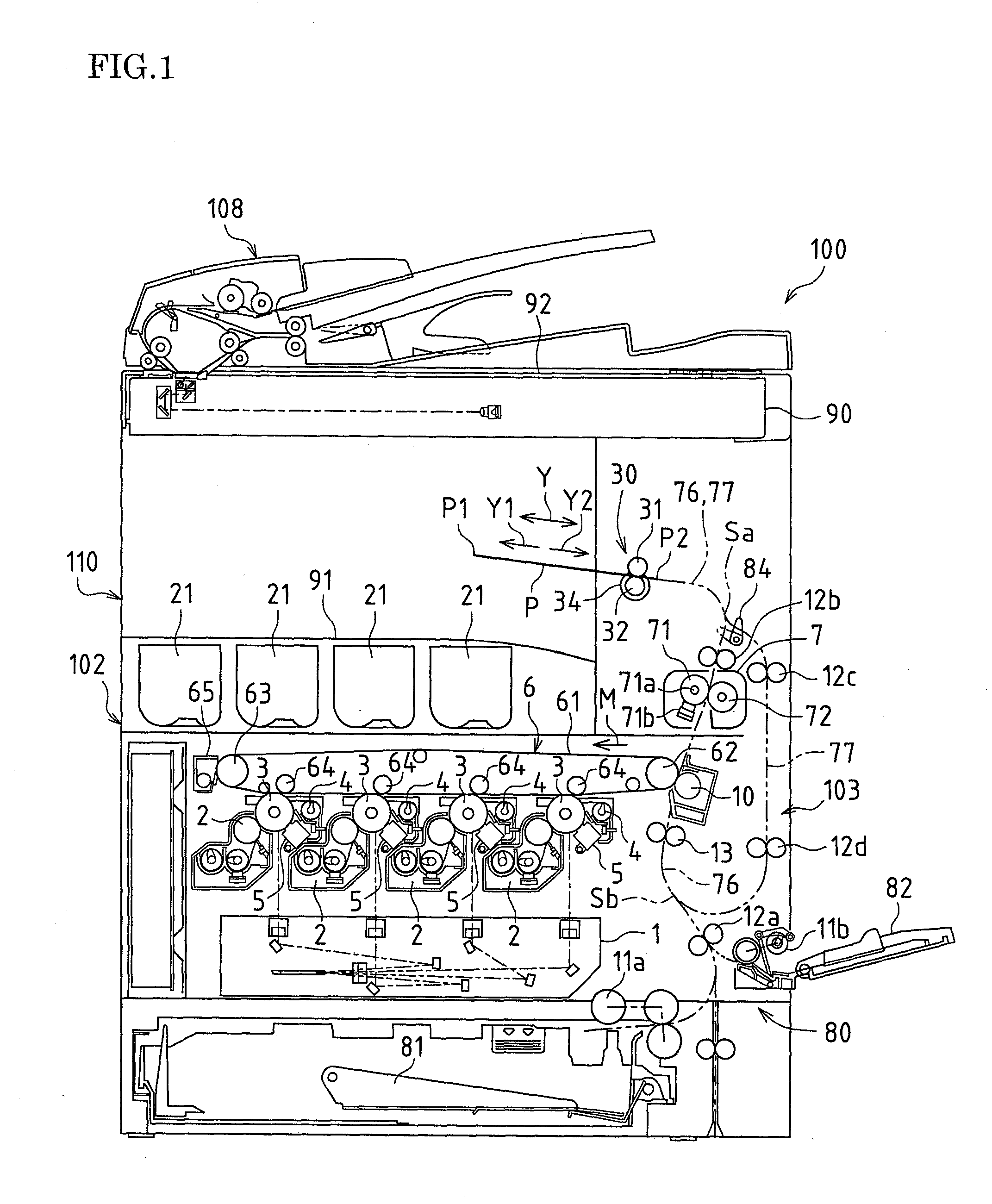
[0134]In Comparative example 1, the image forming apparatus 100 illustrated in FIG. 1 has a configuration where all the individual stiffening rollers 34 integrally rotate with the second discharging rollers 32. In Comparative example 2, the image forming apparatus 100 illustrated in FIG. 1 has a configuration where all the individual stiffening rollers 34 are disposed pivotally around the axis line with respect to the second discharging rollers 32.
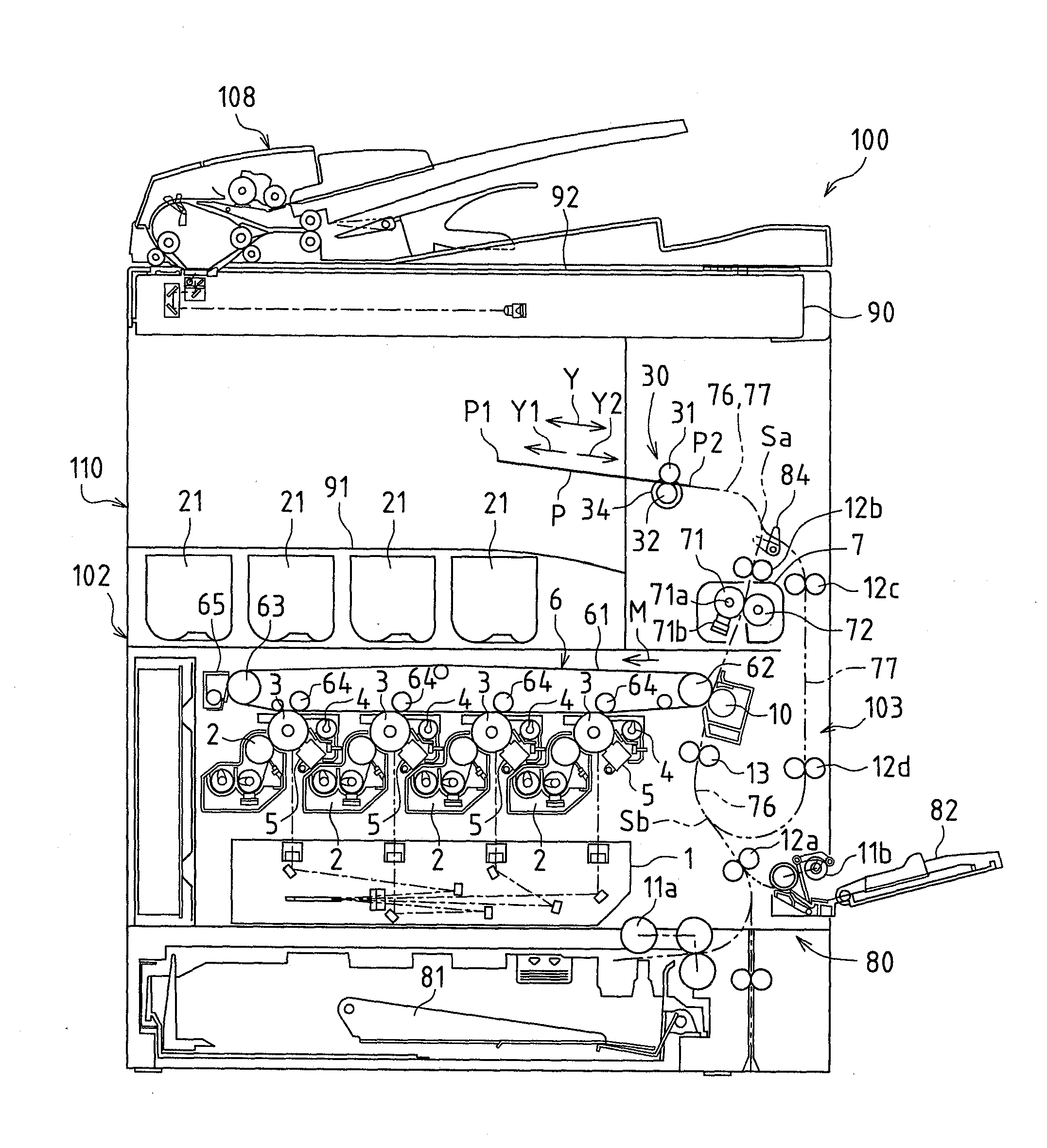
[0135]FIG. 6 is a table illustrating positional relationships and sizes of outer diameters of the stiffening rollers 34 by destination of the image forming apparatus 100.
[0136]As illustrated in FIG. 6, in Japanese (centimeter) specification and North America (inch) specification, outer diameters d1 to ...
PUM
 Abstract
Description
Claims
Application Information
 - R&D
- Intellectual Property
- Life Sciences
- Materials
- Tech Scout
- Unparalleled Data Quality
- Higher Quality Content
- 60% Fewer Hallucinations
Browse by: Latest US Patents, China's latest patents, Technical Efficacy Thesaurus, Application Domain, Technology Topic, Popular Technical Reports.
© 2025 PatSnap. All rights reserved.Legal|Privacy policy|Modern Slavery Act Transparency Statement|Sitemap|About US| Contact US: help@patsnap.com


