Control device and control method for vehicle

a technology of control device and control method, which is applied in the direction of steering initiation, vessel construction, instruments, etc., can solve the problems of difficult elimination of the effect of such steering reaction torque, difficult to keep the vehicle within the target lane, and difficulty in realizing so-called hands-free operation, etc., to achieve the effect of not decreasing the drivability

Active Publication Date: 2013-07-25
TOYOTA JIDOSHA KK
View PDF4 Cites 31 Cited by
  • Summary
  • Abstract
  • Description
  • Claims
  • Application Information

AI Technical Summary

Benefits of technology

[0011]The invention provides a control device and control method for a vehicle that can keep the vehicle within the target lane, without decreasing drivability.

Problems solved by technology

Since the steering reaction torque acts in the direction of interfering with the desired steering angle variation, the vehicle behavior will be disturbed, for example, by steering with the steering input device in the opposite steering direction, and keeping the vehicle within the target lane can be difficult, unless certain measures are taken against such steering reaction torque.
In the device disclosed in JP-A-2007-160998, although a plurality of steering devices, namely, an electric power steering device and a steering angle variation device are used, each device is merely individually responsible for part of the control relating to lane keeping and therefore the effect of such steering reaction torque is difficult to eliminate.
Therefore, in actual operation, the driver should supply to the steering device a steering maintaining torque that acts against such steering reaction torque, and the so-called hands-free operation is difficult to realize.
Therefore, when the driver provides the steering maintaining torque via the steering input device, it is practically close to impossible to eliminate the possibility of the driver getting uncomfortable and the decrease in drivability is difficult to avoid.
Thus, with the device disclosed in JP-A-2007-160998, the decrease in drivability is difficult to avoid when the vehicle is kept within the target lane.

Method used


Image

  • Control device and control method for vehicle
  • Control device and control method for vehicle
  • Control device and control method for vehicle

Examples


Embodiment Construction

[0076]

[0077]An embodiment of the traveling assist device for a vehicle according to the invention will be described below with reference to the appended drawings.

[0078]

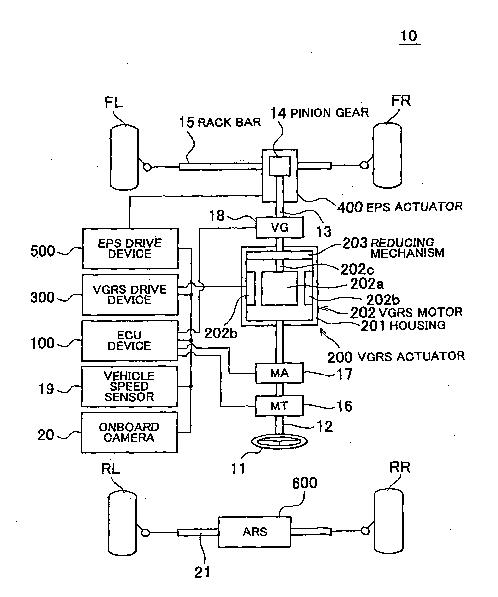
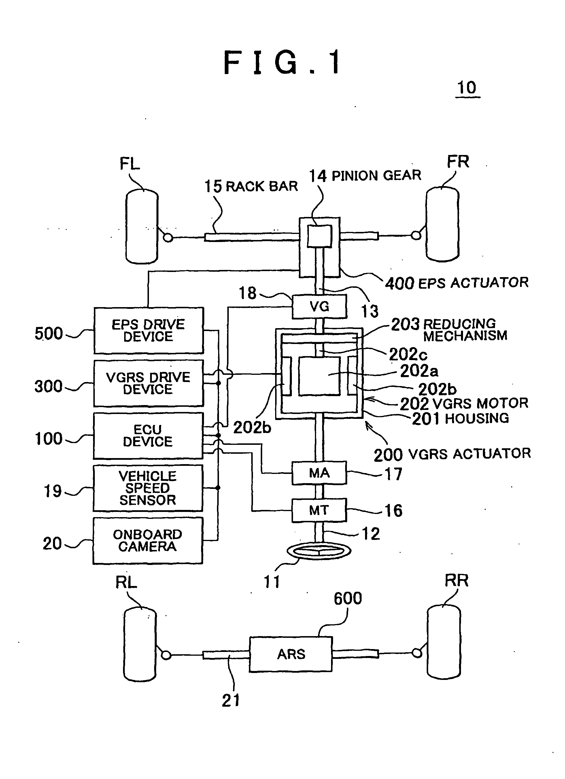
[0079]First, the configuration of a vehicle 10 according to one embodiment of the invention will be described below with reference to FIG. 1. FIG. 1 is a schematic configuration diagram representing schematically the basis configuration of the vehicle 10.

[0080]Referring to FIG. 1, the vehicle 10 is an example of the “vehicle” according to the invention that has a pair of left and right front wheels FL and PR and a pair of left and right rear wheels RL and RR as steered wheels and in which the vehicle advance direction is controlled by steering these steered wheels. The vehicle 10 is provided with an Electronic Control Unit (ECU) 100, a Variable Gear Ratio Steering (VERS) actuator 200, a VGRS drive device 300, an Electronic controlled Power Steering (EPS) actuator 400, an EPS drive device 500, and an Active Rear Steeri...


PUM


Abstract

In control of a vehicle that is provided with a steering torque supply device that supplies a steering torque to a steering device coupled to a steered wheel and a steering transmission ratio variation device that changes a steering transmission ratio, the control includes: setting a target state quantity for keeping the vehicle in a target lane; controlling the steering transmission ratio variation device so that a state quantity of the vehicle becomes the set target state quantity; controlling the steering torque supply device so that a steering reaction restriction torque that restricts a steering reaction torque generated in the steering device is supplied with the steering device as the steering torque when the vehicle is kept within the target lane; and correcting the steering reaction restriction torque on the basis of a steering input when the steering input from a driver of the vehicle is produced.

Description

BACKGROUND OF THE INVENTION[0001]1. Field of the Invention[0002]The invention relates to a technical field of control devices and control methods for vehicles that can perform driver assisted control of various types, such as Lane Keeping Assist (LKA) in a vehicle equipped with various steering assisted devices such. as Electronic controlled Power Steering (EPS), Variable Gear Ratio Steering (VGRS), and Active Rear Steering (ARS).[0003]2. Description of Related Art[0004]The device of such kind that causes the vehicle to perform lane keeping travel by using an electric power steering device and a steering angle variation device has been suggested (see, for example, Japanese Patent Application Publication No. 2007-160998 (JP-A-2007460998)). With the steering control device for a vehicle disclosed in JP-A-2007460998, the electric power steering device is controlled so as to obtain the target steering angle based on the curvature radius during lane keeping travel and the shift of vehicl...

Claims


Application Information

Patent Timeline
Patent Type & Authority Applications(United States)
IPC IPC(8): B62D6/00
CPCB62D5/008B62D5/0472B62D5/005B62D15/025B62D6/00B62D7/159
Inventor LIMPIBUNTERNG, THEERAWATTSUCHIYA, YOSHIAKIASAI, SHOJI
Owner TOYOTA JIDOSHA KK
Why Eureka
Try Eureka