
Surgical Device Including Buttress Material

a surgical device and buttress material technology, applied in the field ofbuttress materials, can solve problems such as the reduction of the diameter of the lumen

Active Publication Date: 2013-08-01
TYCO HEALTHCARE GRP LP
View PDF11 Cites 263 Cited by
  • Summary
  • Abstract
  • Description
  • Claims
  • Application Information

AI Technical Summary

Benefits of technology

The present disclosure provides a surgical stapling device with a support member for attaching a buttress material to the device. The support member can be a separate attachment or a part of the device itself. The buttress material is positioned between the anvil assembly and the cartridge assembly of the device and is attached to the support member. The buttress material is used to reinforce the staple line and improve the quality of tissue joining. The device also includes an elongate member that extends from the tubular body portion of the device and is used to support and attach the buttress material. The method of using the buttress material involves positioning it between the anvil assembly and the cartridge assembly, securing it to the support member, and then using the device to join tissue portions. The elongate member can have a circular platform or a distal portion with an outer diameter larger than the proximal portion, and the buttress material can be adhered to the support member or the distal portion. The method also includes the steps of positioning the buttress material, grasping the tissue between the anvil assembly and the cartridge assembly, and firing the device to drive the staples through the buttress material and the tissue to secure the first portion of the buttress material to the body tissue.

Problems solved by technology

One possible side effect of any end-to-end bowel anastomosis is its tendency to undergo stenosis, which can decrease the diameter of the lumen over time.

Method used


Image

  • Surgical Device Including Buttress Material
  • Surgical Device Including Buttress Material
  • Surgical Device Including Buttress Material

Examples


Embodiment Construction

[0035]Embodiments of the presently disclosed annular surgical stapling device will now be described in detail with reference to the drawing figures wherein like reference numerals identify similar or identical elements. As used herein and as is traditional, the term “distal” refers to that portion which is furthest from the user while the term “proximal” refers to that portion which is closest to the user.

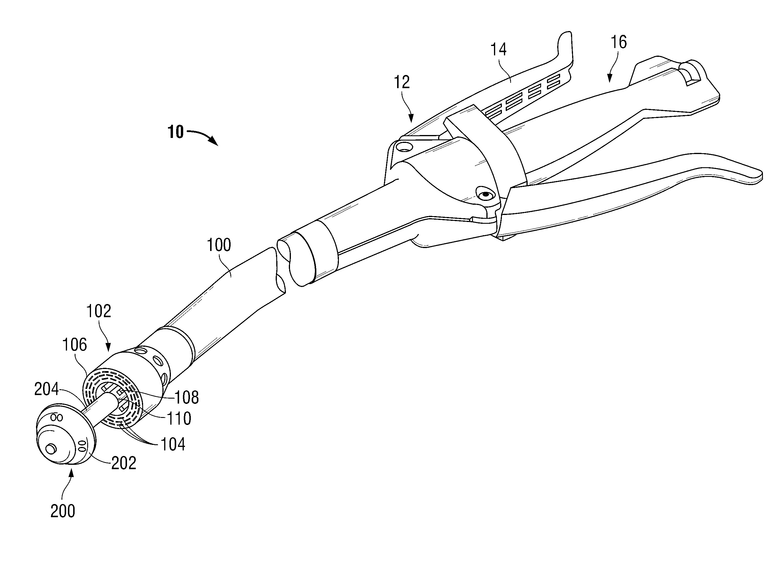
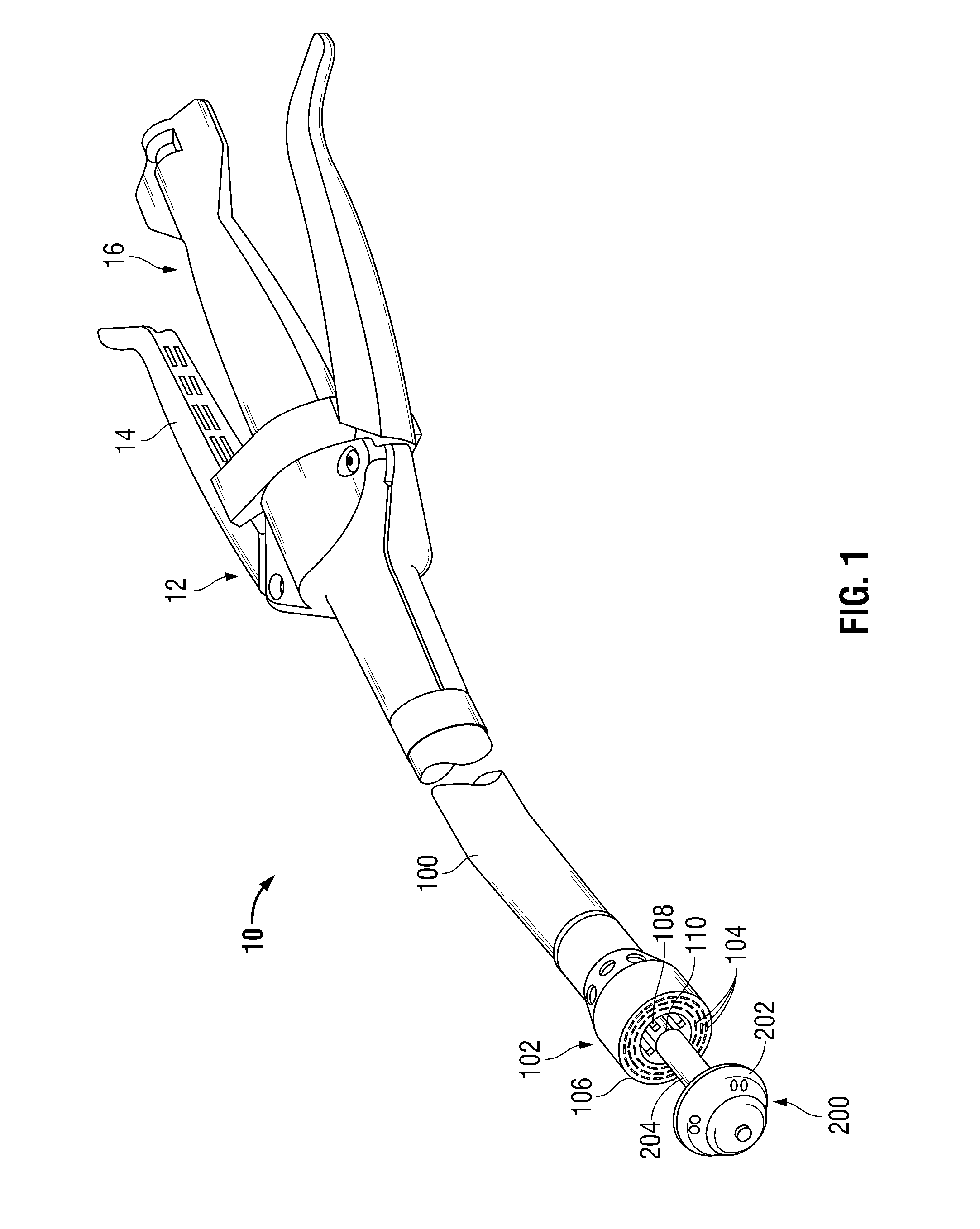
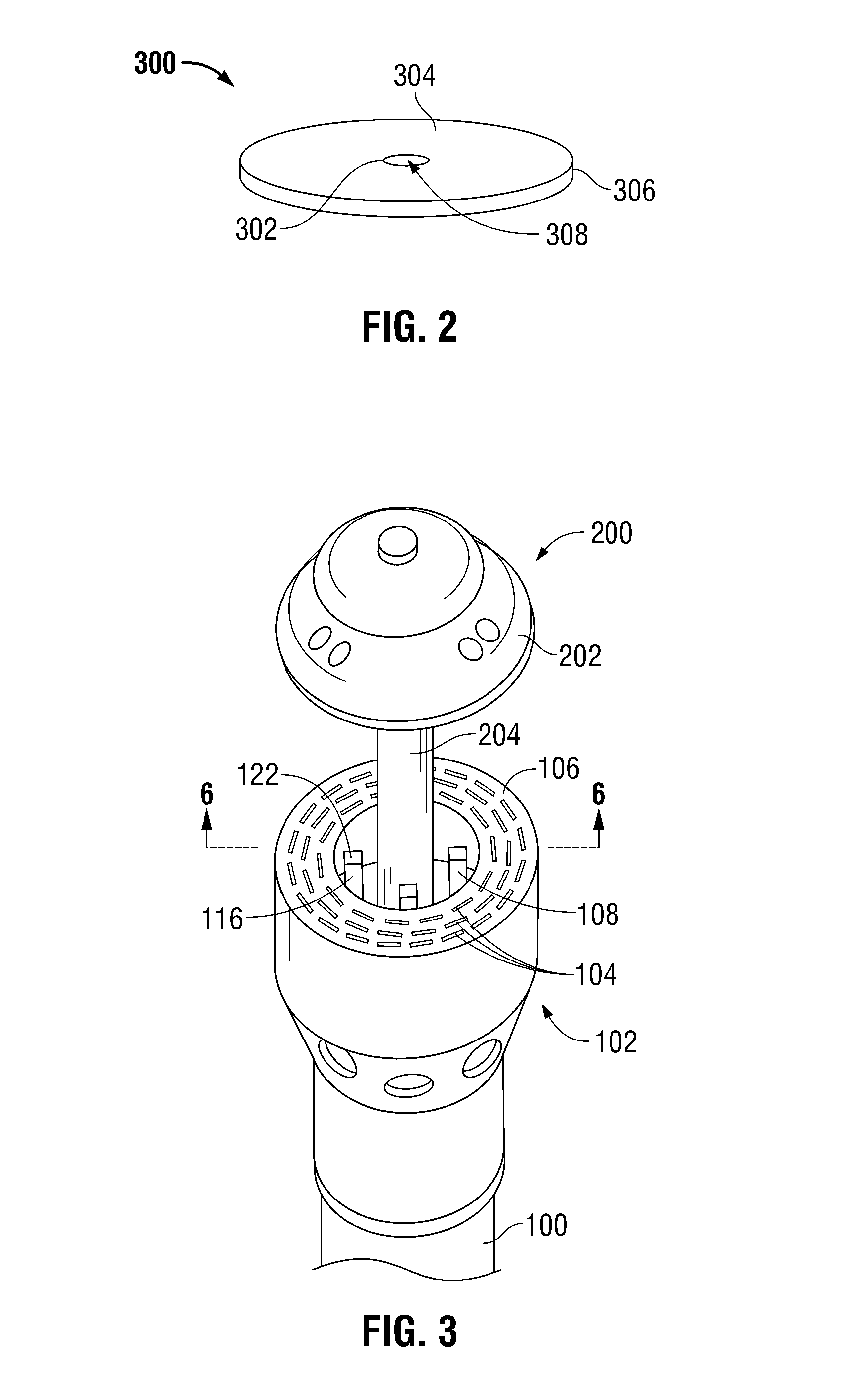
[0036]Referring initially to FIG. 1, an annular surgical stapling device for use with a buttress material is disclosed herein and is generally designated as 10. Surgical stapling device 10 includes a handle assembly 12 having at least one pivotable actuating handle member 14, and an advancing member 16. Extending from handle member 12, there is provided a tubular body portion 100 which may be constructed so as to have a curved shape along its length. Body portion 100 terminates in a staple cartridge assembly 102 which includes at least one annular array of staple receiving slots 10...


PUM

PropertyMeasurementUnit
Diameteraaaaaaaaaa

Abstract

The present disclosure provides a surgical stapling device and a method for joining tissue portions. The surgical stapling device includes a handle assembly and a tubular body portion supported on a distal end of the handle assembly having a staple cartridge assembly containing a plurality of surgical staples in an annular array. An anvil assembly is at a distal end of the stapling device and has a shaft for removably connecting the anvil assembly to the tubular body portion. The anvil assembly and tubular body portion are juxtaposed with respect to one another along the shaft and are arranged so as to be approximated with respect to one another. A support member extends from the tubular body portion towards the anvil assembly and a buttress material is supported by the support member and removably attached to the support member.

Description

BACKGROUND[0001]1. Technical Field[0002]The present disclosure relates to buttress materials for use with a surgical stapling device and, more particularly, to a method and structure for attaching a buttress material to a surgical stapling device for use in anastomosis procedures.[0003]2. Background of Related Art[0004]Staples have traditionally been used to replace suturing when joining or anastomosing various body structures such as, for example, the bowel or bronchus. The surgical stapling devices employed to apply these staples are generally designed to simultaneously cut and seal an extended segment of tissue in a patient, thus vastly reducing the time and risks of such procedures.[0005]Linear or annular surgical stapling devices are employed by surgeons to sequentially or simultaneously apply one or more linear rows of surgical fasteners, e.g., staples or two-part fasteners, to body tissue for the purpose of joining segments of body tissue together and / or for the creation of a...

Claims


Application Information

Patent Timeline
IPC IPC(8): A61B17/068
CPCA61B17/07292A61B17/1155A61B17/115A61B2017/07214A61B17/068A61B17/105
Inventor CASASANTA, JR., THOMASMIESSE, ANDREWCARTER, SALLY
Owner TYCO HEALTHCARE GRP LP
Learn More