Fishing lure with fin

a technology of fishing lures and fins, applied in the field of fishing tackles, can solve the problems of unstable fishing lures and erratic movement of fishing lures, and achieve the effect of more induced motion

Inactive Publication Date: 2013-08-15
SIMMONS DAVID L
View PDF0 Cites 0 Cited by
  • Summary
  • Abstract
  • Description
  • Claims
  • Application Information

AI Technical Summary

Benefits of technology

[0012]The fin member is a sheet that is substantially planar. The fin extends substantially perpendicular relative to the flat surface of the body. The fin protrudes normal to the flat surface of the body and obliquely to the longitudinal axis of the shaft of the hook. In various embodiments, the angle between the fin and the longitudinal axis of the shaft varies between 10 and 70 degrees, with smaller oblique angles resulting in more induced motion. In one such embodiment, a orthographic projection of the fin onto the flat surface of the body defines an oblique angle of 45 degrees relative to the longitudinal axis of the shaft of the fishing hook. When the tackle is pulled through water, the water impinges the fin, which deflects the water and causes the tackle to be unstable and move about with an erratic motion.

Problems solved by technology

When the tackle is pulled through water, the water impinges the fin, which deflects the water and causes the tackle to be unstable and move about with an erratic motion.

Method used


Image

  • Fishing lure with fin
  • Fishing lure with fin
  • Fishing lure with fin

Examples


second embodiment

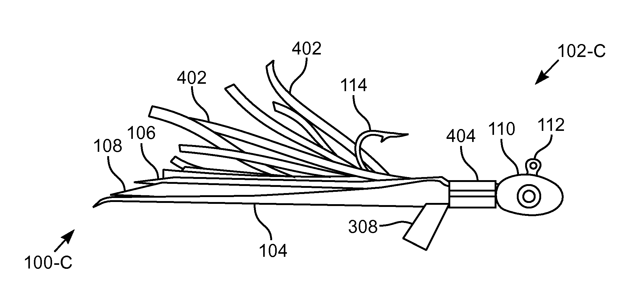
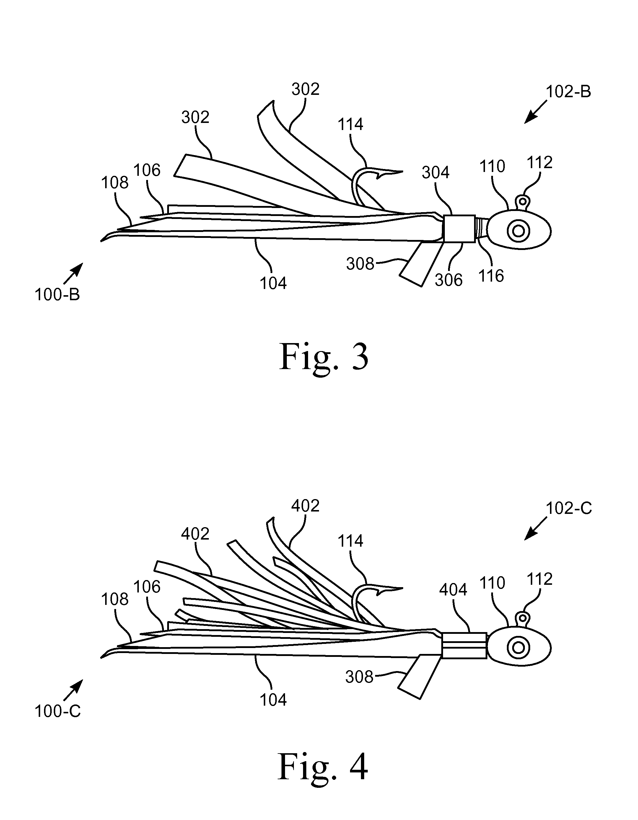
[0068]FIG. 9 illustrates a plan view of a fin assembly 304′. The illustrated embodiment has a single fin 308′ having a polygonal shape. The polygonal shape of the fin 308′ provides for a different movement of the lure 102 in the water than with the V-shaped fins 308. In various embodiments, the fin 308′ has various shapes, for example, regular and irregular polygons, and oval. The illustrated embodiment is suitable for mounting in the trailing position, as illustrated in FIGS. 3 & 4, or in a leading position where the fin 308′ is positioned forward of the tab 306 and / or the iridescent tail 100.

third embodiment

[0069]FIG. 10 illustrates a perspective view of a fin assembly 304″. In this embodiment, the single fin 308″ has a rectangular shape that extends downward away from the shank 208 when the fin assembly 304″ is attached to the lure 102. The tab 306′ has a half-cylindrical shape that is suitable for being captured by the connector 404 as illustrated in FIG. 4.

[0070]FIG. 11 illustrates a perspective view of one embodiment of a tackle 1100-A that is a lure with a fin 1112-A. Fishing tackle 1100 includes lures, sinkers, and other devices that are used when fishing to attract and entice fish to strike. Fish are attracted to tackle 1100 that moves in a manner that simulates the movement of bait, be it a fish or an insect or other animal. The illustrated lure 1100-A includes eyes 1122 that give the lure 1100-A the appearance of a bait fish. In such an embodiment, the body 1102 is colored to simulate a fish and reflective sheet 1116 simulates the scales of a fish.

[0071]The tackle 1100-A illus...


PUM


Abstract

An apparatus for attracting fish by inducing motion in the water. The tackle includes a fin that imparts motion to the tackle when the tackle is deployed and moves relative to water. A weighted body having a cabochon shape includes a fin member that extends perpendicular to a flat surface of the body. The tackle includes a fish hook oriented such that the fin is positioned between the barb and the shaft of the fish hook. In various embodiments, the hook shaft and fin are on the same side of the body or opposite sides. In other embodiments, the fin is attached to the flat surface or the ovoid surface of the body, either directly or in a channel.

Description

CROSS-REFERENCE TO RELATED APPLICATIONS[0001]This application is a continuation-in-part of prior application Ser. No. 13 / 493,072, filed Jun. 11, 2012, which is a continuation of prior application Ser. No. 12 / 857,221, filed Aug. 16, 2010, issued as U.S. Pat. No. 8,196,337 on Jun. 12, 2012, which is a continuation-in-part of prior application Ser. No. 11 / 846,599, filed Aug. 29, 2007, issued as U.S. Pat. No. 7,774,974 on Aug. 17, 2010.STATEMENT REGARDING FEDERALLY SPONSORED RESEARCH OR DEVELOPMENT[0002]Not ApplicableBACKGROUND OF THE INVENTION[0003]1. Field of Invention[0004]This invention pertains to fishing tackle. More particularly, this invention pertains to tackle that attracts fish by motion induced by a fin attached to a body.[0005]2. Description of the Related Art[0006]Fishing is both a sport and a livelihood for many. To catch fish with a hook, the fish must be enticed to strike the hook such that the barb of the hook impales the flesh of the fish. To entice fish, hooks often ...

Claims


Application Information

Patent Timeline
Patent Type & Authority Applications(United States)
IPC IPC(8): A01K85/02
CPCA01K85/00A01K85/02A01K85/12A01K85/01
Inventor SIMMONS, DAVID L.
Owner SIMMONS DAVID L
Why Eureka
Try Eureka