Configurable Pod Structure and Store Stowage and Deployment System and Method

a pod structure and configuration technology, applied in the field of storage stowage and deployment systems and methods, can solve the problems of affecting the aircraft's performance characteristics, reducing range, acceleration, top speed, and difficult to retrofit such internal storage or weapons bays or carriages onto an existing aircra

Active Publication Date: 2013-08-29
THE BOEING CO
View PDF20 Cites 68 Cited by
  • Summary
  • Abstract
  • Description
  • Claims
  • Application Information

AI Technical Summary

Benefits of technology

[0009]This need for externally mounted, internally configurable store stowage and deployment devices, systems and methods is satisfied. As discussed in the below detailed description, embodiments of the externally mounted, internally configurable store stowage and deployment devices, systems and methods may provide significant advantages over known devices, systems, and methods.

Problems solved by technology

However, internal carriage of stores occupies valuable aircraft volume and leads to design compromises that may affect the aircraft's performance characteristics.
The design tradeoffs that result may have an impact on the aircraft performance, for example, reduced range, acceleration, and top speed.
Moreover, known internal stores or weapons bays may require a design as part of a new aircraft as it may be difficult to retrofit such internal stores or weapons bay or carriage onto an existing aircraft.
However, like radar signature, such known external store carriage systems may create negative effects on the aerodynamic performance of the military aerial vehicles due to increased aerodynamic drag.
Finally, the internal configuration and door opening mechanisms of known external store carriage systems may not provide sufficient clearance for a store to be separately ejected without interference from the other stores if a store ejector device fails to deploy a store or there is a some other problem with a store deploying.

Method used


Image

  • Configurable Pod Structure and Store Stowage and Deployment System and Method
  • Configurable Pod Structure and Store Stowage and Deployment System and Method
  • Configurable Pod Structure and Store Stowage and Deployment System and Method

Examples


Embodiment Construction

[0055]Disclosed embodiments will now be described more fully hereinafter with reference to the accompanying drawings, in which some, but not all of the disclosed embodiments are shown. Indeed, several different embodiments may be provided and should not be construed as limited to the embodiments set forth herein. Rather, these embodiments are provided so that this disclosure will be thorough and complete and will fully convey the scope of the disclosure to those skilled in the art.

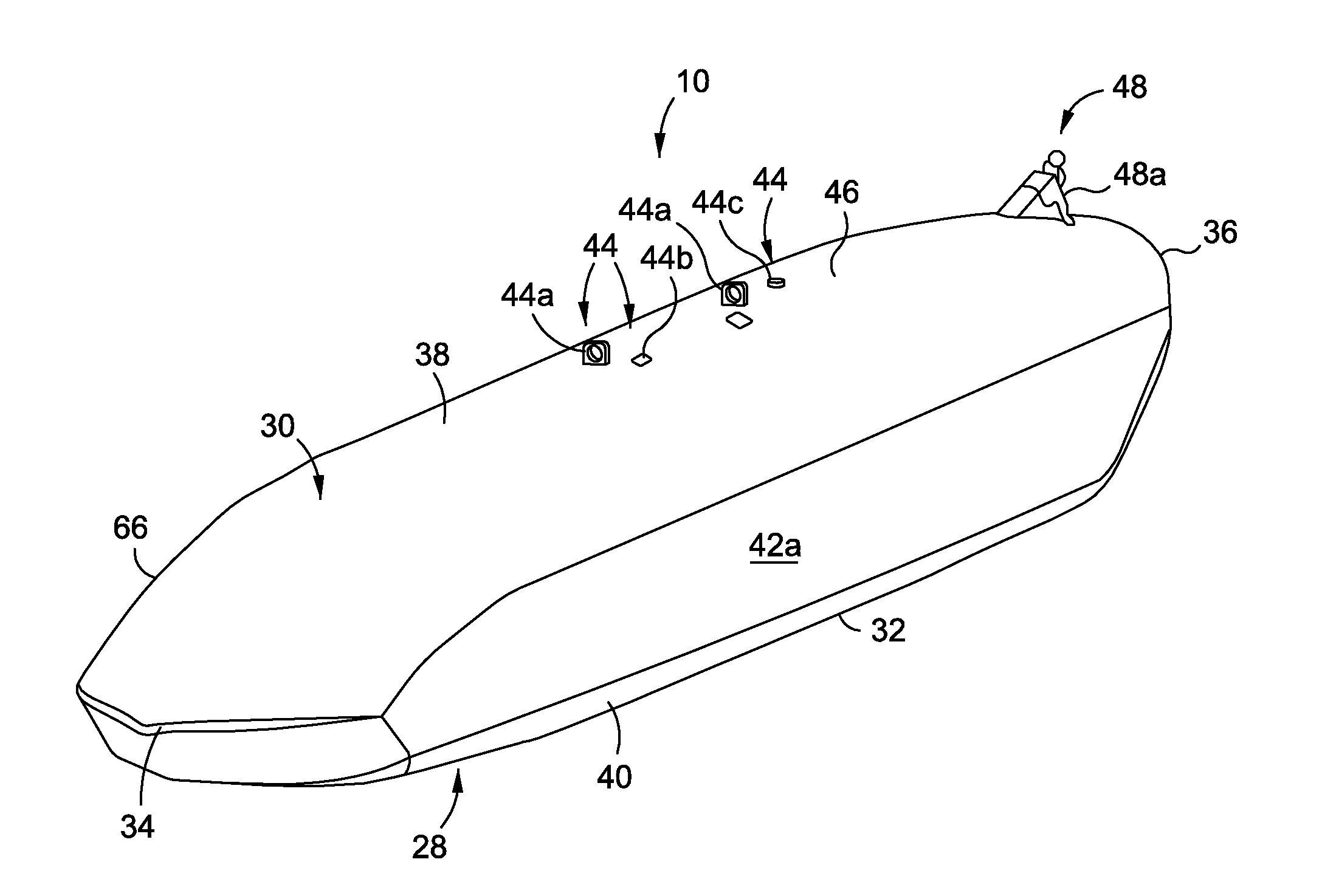
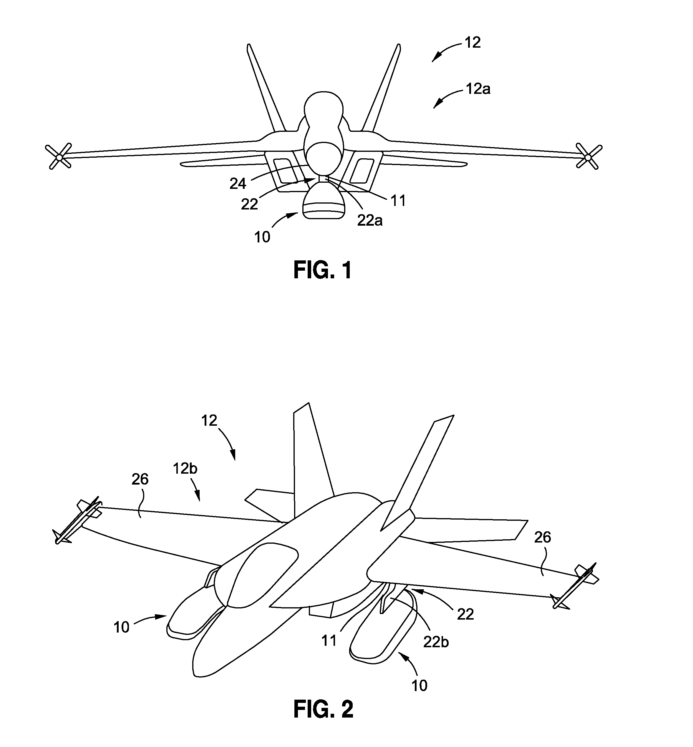
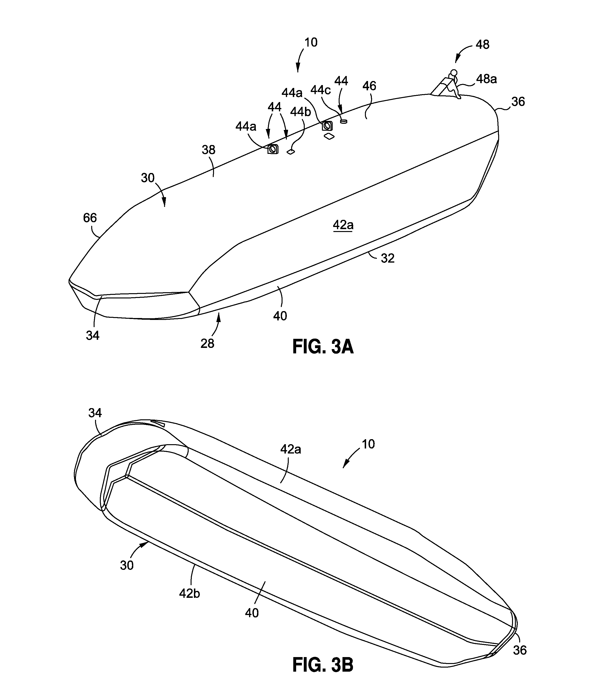
[0056]Now referring to the Figures, in an embodiment of the disclosure, there is provided a pod structure 10 (see FIGS. 3A, 5, 6B), discussed in further detail below. The pod structure 10 is externally mountable, and is preferably externally mountable to an exterior portion 11 of an aerial vehicle 12 (see FIGS. 1A, 2A). The pod structure 10 is internally configurable and optimized for internal placement of one or more deployable stores 14 (see FIGS. 1A, 2A, 3D) through configuration in a configurable inter...


PUM


Abstract

In one embodiment there is provided a radar signature and induced aerodynamic drag minimizing, externally mountable, internally configurable pod structure optimized for internal placement of one or more deployable stores through configuration and optimal kinematic operation of a pod door assembly. The pod structure has an externally mountable pod housing, a predetermined pod housing cross-sectional configuration optimized to provide a configurable interior volume accommodating multiple different store configurations, and a predetermined pod housing configuration having a cross-sectional configuration optimized to minimize a radar signature and an induced aerodynamic drag. The pod structure further has a pod door assembly integral with the pod housing and having a plurality of pod doors and one or more seal door mechanism assemblies. The pod structure is optimized in kinematic operational combination of the pod doors and seal door mechanism assemblies controlling ejection launch envelopes.

Description

BACKGROUND[0001]1) Field of the Disclosure[0002]The disclosure relates generally to store stowage and deployment systems and methods, and more particularly, to externally mounted store stowage and deployment systems and methods for use on aerial vehicles, such as stealth and military aircraft.[0003]2) Description of Related Art[0004]Store stowage and deployment systems are commonly used on stealth and military aircraft to carry and release missiles, bombs, and other weapons and materials, generally referred to as “stores”. Such store stowage and deployment systems are typically mounted on an underside of the aircraft, such as on a wing pylon or within a fuselage bay.[0005]A primary mission of stealth aircraft is typically to perform a mission, such as deploying stores, while avoiding a target's sensors, such as radar. Known stealth aircraft exist that internally stow mission stores within the aircraft in order to minimize a radar signature. However, internal carriage of stores occup...

Claims


Application Information

Patent Timeline
Patent Type & Authority Applications(United States)
IPC IPC(8): B64D1/08B64D1/04
CPCF41F3/065B64D7/08
Inventor BINKHOLDER, RYANFOSTER, JOHN K.
Owner THE BOEING CO
Why Eureka
Try Eureka