Arc Fault Detection

a fault detection and arc technology, applied in short-circuit testing, emergency protective circuit arrangements, instruments, etc., can solve the problems of significant damage, energy discharge can cause extensive damage,

Active Publication Date: 2013-08-29
INNOVATIVE SCI SOLUTIONS
View PDF2 Cites 40 Cited by
  • Summary
  • Abstract
  • Description
  • Claims
  • Application Information

AI Technical Summary

Problems solved by technology

When power that is discharged by an arc is large, extensive damage can result from the discharge of energy.
Additionally, even when the power discharge is small, significant damage can result if arcing occurs over an extended period of time.

Method used


Image

  • Arc Fault Detection
  • Arc Fault Detection
  • Arc Fault Detection

Examples


Embodiment Construction

[0033]The phenomena of electrical arcing can be utilized in beneficial ways—for example, as a source of heat for foundry arc heaters and as a source of light in high-pressure arc lamps, etc. An electrical arc fault is an unwanted electrical discharge between two conductors. Most electrical arcs are characterized by a high localized gas temperature that is likely to cause localized physical damage. When the power dissipated within an arc is small, damage is typically minimal in the short term but may become significant over an extended period of time. When considerable power is involved, extensive damage over a wide area can occur in a relatively short period of time.

[0034]The value of a circuit device that is capable of interrupting electrical arcs has been recognized since the 1920's. For example, in 1938, W. H. Frank and L. E. Fisher patented an “Electrical Distribution System,” (U.S. Pat. No. 2,116,676) for a device to minimize arc damage and extinguish arcing faults. To be usefu...


PUM


Abstract

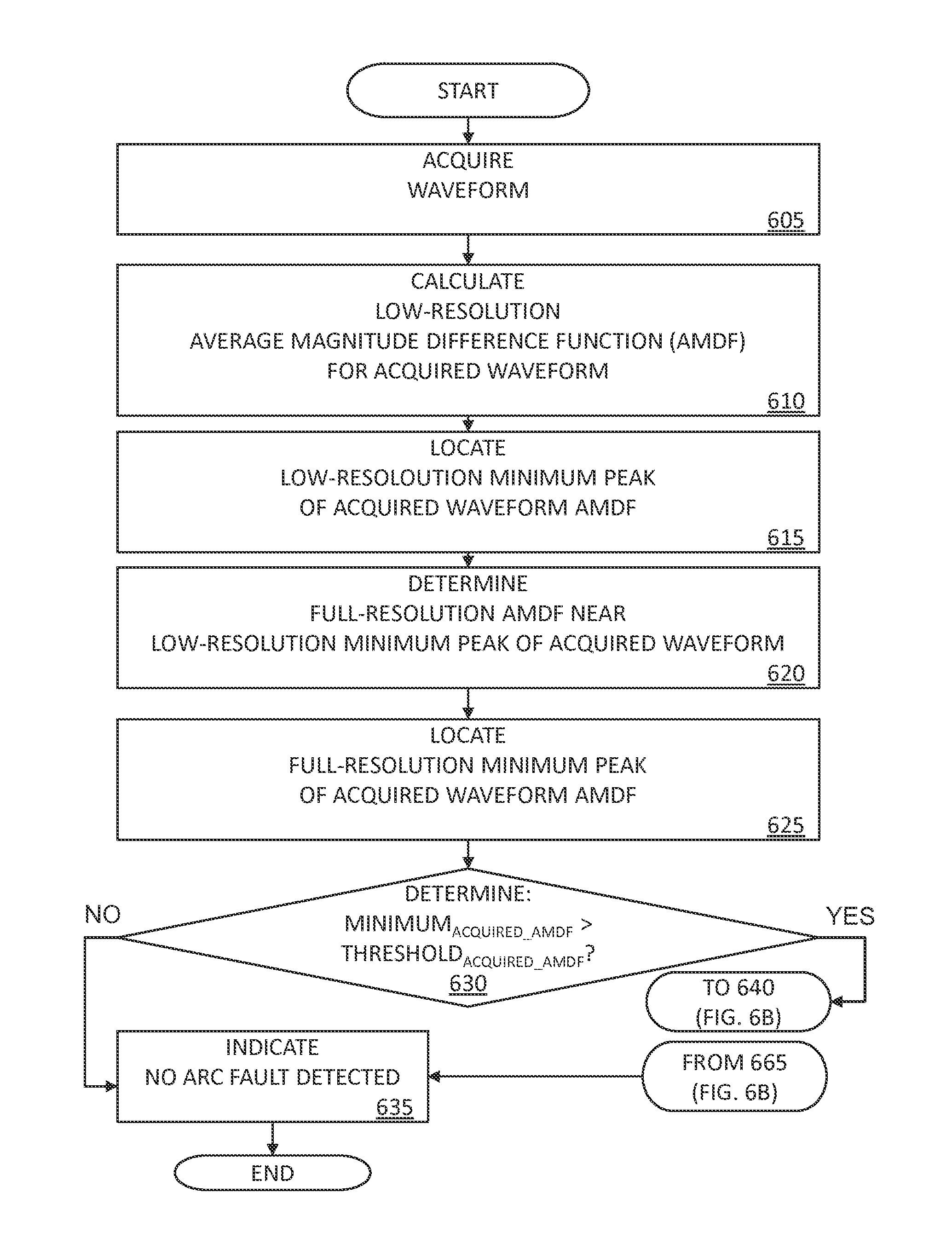
The present disclosure provides systems and methods for detecting arc faults. For some embodiments, arc faults are detected from waveforms that are acquired and processed, preferably using an Average Magnitude Difference Function (AMDF). The characteristics of the waveform provide an indication of whether or not an arcing fault occurred.

Description

CROSS REFERENCE TO RELATED APPLICATIONS[0001]This application claims the benefit of U.S. provisional patent application Ser. No. 61 / 604,829, filed 2012 Feb. 29, having the title “Method of Arc Fault Detection,” which is incorporated herein by reference in its entirety.BACKGROUND[0002]1. Field of the Disclosure[0003]The present disclosure relates generally to arc faults and, more particularly, to systems and methods for detecting arcing faults.[0004]2. Description of Related Art[0005]Electrical arcing is the electrical discharge between two conductors. While electrical arcing can be useful, such as in arc-welding and for use in high-pressure arc lamps, undesired electrical discharges are known as arc faults. When power that is discharged by an arc is large, extensive damage can result from the discharge of energy. Additionally, even when the power discharge is small, significant damage can result if arcing occurs over an extended period of time. Thus, there are ongoing efforts to mit...

Claims


Application Information

Patent Timeline
Patent Type & Authority Applications(United States)
IPC IPC(8): G01R31/02
CPCG01R31/12G01R31/024G01R31/52H02H1/0015H02H3/40
Inventor GROSJEAN, DENNIS F.
Owner INNOVATIVE SCI SOLUTIONS
Why Eureka
Try Eureka