System and method for geo-locating and detecting source of electromagnetic emissions

a technology of electromagnetic emission and geolocation, applied in direction finders, instruments, measurement devices, etc., can solve the problem that electronic devices necessarily emit electro-magnetic radiation unintentionally

Active Publication Date: 2013-09-05
NOKOMIS
View PDF20 Cites 30 Cited by
  • Summary
  • Abstract
  • Description
  • Claims
  • Application Information

AI Technical Summary

Problems solved by technology

As is further generally well known, any electronic device necessarily emits electro-magnetic radiation unintentionally.

Method used


Image

  • System and method for geo-locating and detecting source of electromagnetic emissions
  • System and method for geo-locating and detecting source of electromagnetic emissions
  • System and method for geo-locating and detecting source of electromagnetic emissions

Examples


Embodiment Construction

[0041]Prior to proceeding to the more detailed description of the present invention, it should be noted that, for the sake of clarity and understanding, identical components which have identical functions have been identified with identical reference numerals throughout the several views illustrated in the drawing figures.

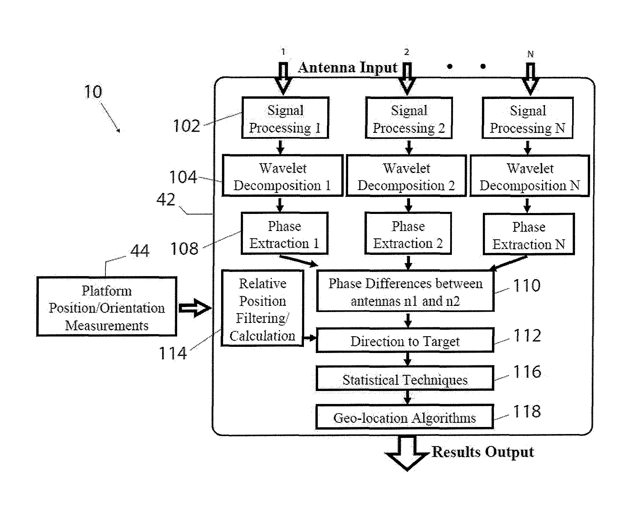
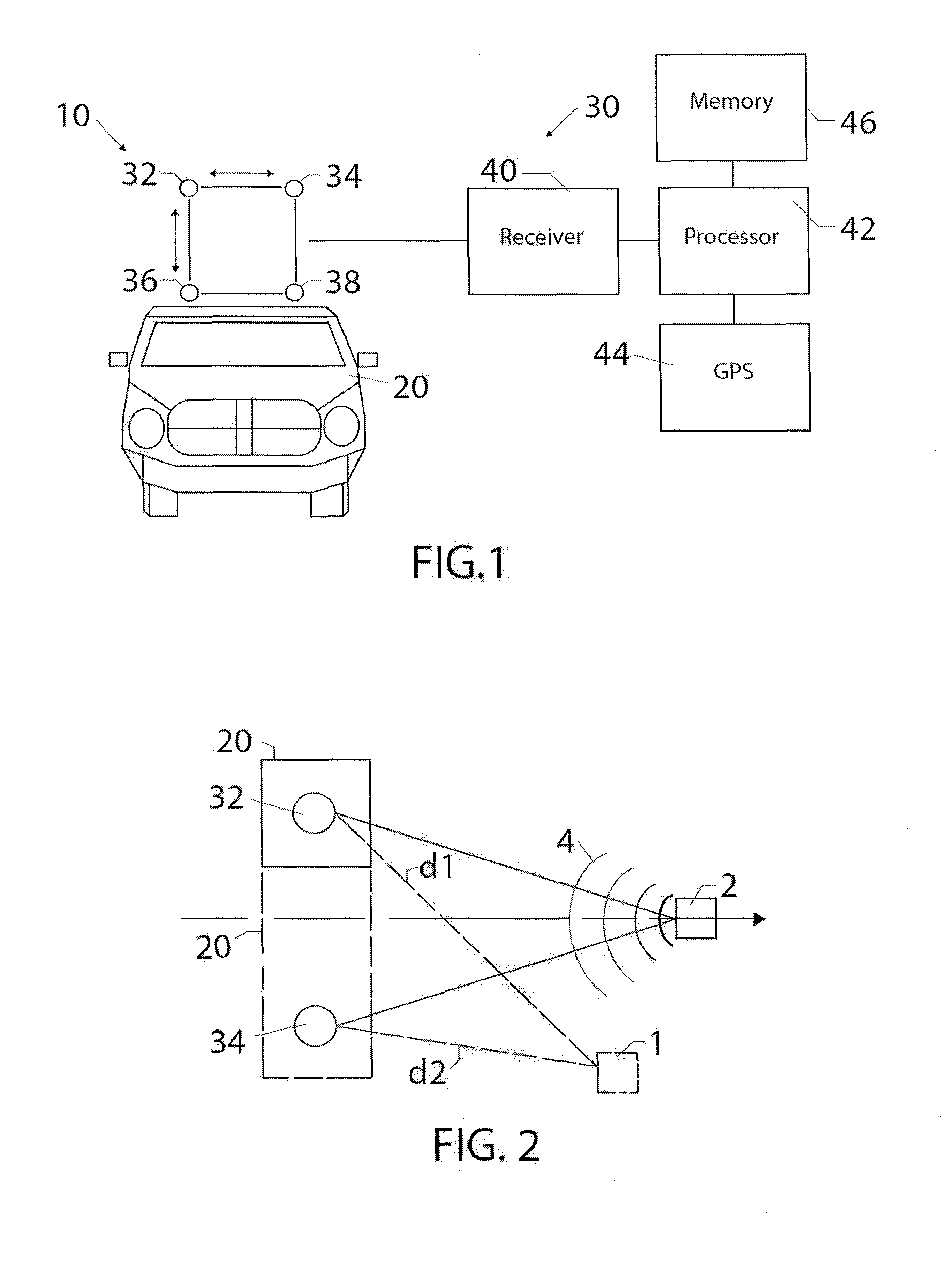
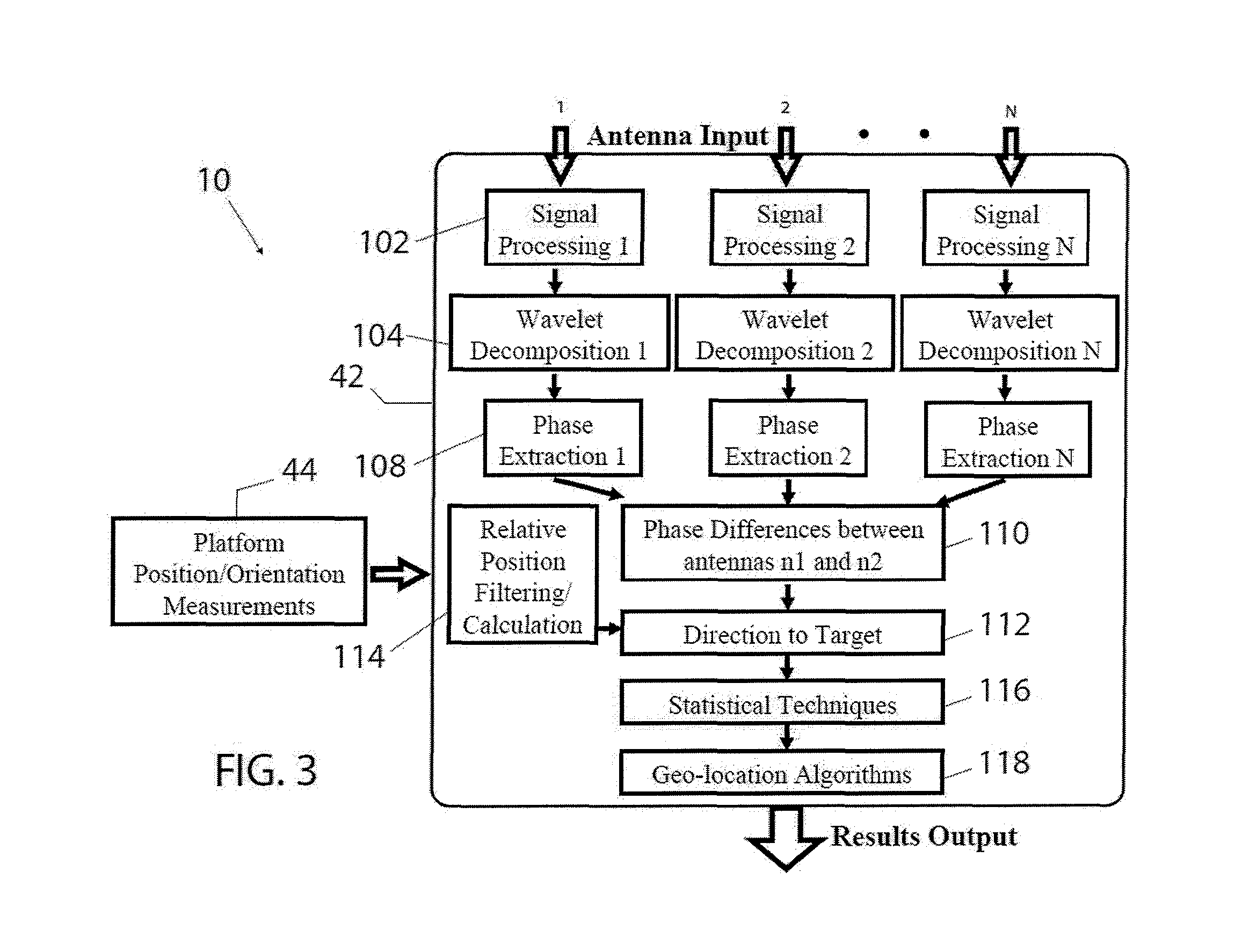
[0042]The present invention describes a system, generally designated as 10, and method for identifying a real-world geographic location of an emission source (or target) 2 emitting electromagnetic energy 4. Preferably, the emission source 2 is a stationary emission source. The electromagnetic emission is preferably of a Radio Frequency (RF) type and is one of intentional or unintentional, although other types of electromagnetic emission are also contemplated in the instant invention.

[0043]Now in reference to FIGS. 1-18, the system 10 includes a platform 20 configured for movement. Such platform 20 may be provided as a vehicle having motive power, as shown in FIG. 1...


PUM


Abstract

A system for identifying a real-world geographic location of an emission source emitting electromagnetic energy includes a platform configured for movement and an apparatus disposed on the platform and configured to collect and process, in a passive manner and during movement of the platform, at least a pair of successive samples of the electromagnetic energy emission and define angular and spatial coordinates of the emission source. The apparatus includes at least a pair of antennas, a receiver coupled to antennas and a processor executing a predetermined logic.

Description

STATEMENT REGARDING FEDERALLY SPONSORED RESEARCH AND DEVELOPMENT[0001]This invention was made with government support under Small Business Innovative Research (SBIR) Contract FA8650-08-C-1402 awarded by the United States Air Force. The government has certain rights in the invention.CROSS REFERENCE TO RELATED APPLICATIONS[0002]N / AFIELD OF THE INVENTION[0003]The present invention relates, in general, to geo-location of sources of electromagnetic energy emissions, and, more particularly, this invention relates to geo-location of electronics and electronic devices and, yet more particularly, the instant invention relates to geo-location of electronics and electronic devices through collection and processing of unintended electromagnetic radiation given off by the electronics and electronic devices.REFERENCE TO SEQUENCE LISTING, A TABLE, OR A COMPUTER PROGRAM LISTING COMPACT DISC APPENDIX[0004]N / ABACKGROUND OF THE INVENTION[0005]As is generally known, ability to geo-locate and detect ele...

Claims


Application Information

Patent Timeline
Patent Type & Authority Applications(United States)
IPC IPC(8): G01S5/02
CPCG01S5/0221G01S5/0278G01S5/04G01S5/0294G01S5/0284G01S5/02213G01S19/24G01S3/46G01S19/21
Inventor PARKS, BRANDON SCOTTKELLER, III, WALTER J.HSU, JENNTING TIMOTHY
Owner NOKOMIS
Why Eureka
Try Eureka